Ring-type fan and impeller structure thereof

a technology of ring-type fans and impellers, which is applied in the direction of liquid fuel engines, vessel construction, marine propulsion, etc., can solve the problems of reducing the heat dissipation efficiency and performance of ring-type fans, affecting the safety and performance of the whole system, and consuming more power and generating more heat during operation, so as to reduce the formation of negative pressure and increase the heat dissipation performance

Active Publication Date: 2016-01-12
ASIA VITAL COMPONENTS SHENZHEN CO LTD
View PDF10 Cites 4 Cited by
  • Summary
  • Abstract
  • Description
  • Claims
  • Application Information

AI Technical Summary

Benefits of technology

[0007]A primary object of the present invention is to provide an impeller structure for ring-type fan that is able to minimize the forming of negative pressure at an air outlet of the fan, so that the ring-type fan can have upgraded heat dissipation performance.
[0008]Another object of the present invention is to provide an impeller structure for ring-type fan that also helps in removing heat from surrounding electronic elements.
[0009]A further object of the present invention is to provide a ring-type fan that is able to minimize the forming of negative pressure at an air outlet thereof, so that the ring-type fan can have upgraded heat dissipation performance.
[0010]A still further object of the present invention is to provide a ring-type fan that also helps in removing heat from surrounding electronic elements.
[0011]To achieve the above and other objects, the impeller structure for ring-type fan according to the present invention includes an impeller assembly having a hub, a plurality of impellers outward extended from and spaced around the hub, and a ring member connected to radially outer ends of the impellers and having a stop section formed around an outer side thereof. When a ring-type fan using the impeller structure of the present invention operates, air flows through the impeller structure from a front side to a rear side thereof. Any backflow of the air flowed through the impeller structure would be stopped by the stop section from interfering with the inflow of air. In this manner, it is possible to minimize the forming of negative pressure at the rear side of the impeller structure and thereby increase the heat dissipation performance of the ring-type fan.
[0013]With the above arrangements, when the ring-type fan of the present invention operates, air outside the frame is sucked into the receiving space via the air inlet and then flows out of the frame 20 via the air outlet. At this point, a part of the air will form backflows at the air outlet. The backflows will sequentially pass the air passage and the airflow guides to finally flow to an outer side of the frame without interfering the inflow of air. In this manner, it is possible to minimize the forming of negative pressure at the air outlet of the ring-type fan and thereby increase the heat dissipation performance of the ring-type fan.

Problems solved by technology

While the currently available electronic devices have faster and faster data processing speed, they also consume more power and produce more heat during operation.
The produced high amount of heat must be timely removed from the electronic devices, lest the raised temperature should cause burnout of the CPU and other electronic elements to adversely influence the whole system safety and performance.
The backflows pass through the clearance between the ring member and the frame to interfere with inflow of air and cause unsmooth flowing of outflow of air, resulting in lowered heat dissipation efficiency and performance of the ring-type fan and reduced service life thereof.
Accordingly, the prior art ring-type fan has the following disadvantages: (1) lowered heat dissipation efficiency; and (2) reduced fan performance.

Method used


Image

  • Ring-type fan and impeller structure thereof
  • Ring-type fan and impeller structure thereof
  • Ring-type fan and impeller structure thereof

Examples


Embodiment Construction

[0027]The present invention will now be described with some preferred embodiments thereof and with reference to the accompanying drawings. For the purpose of easy to understand, elements that are the same in the preferred embodiments are denoted by the same reference numerals.

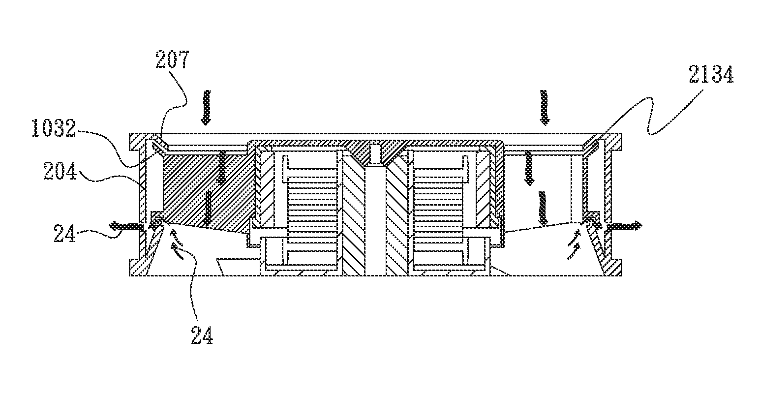
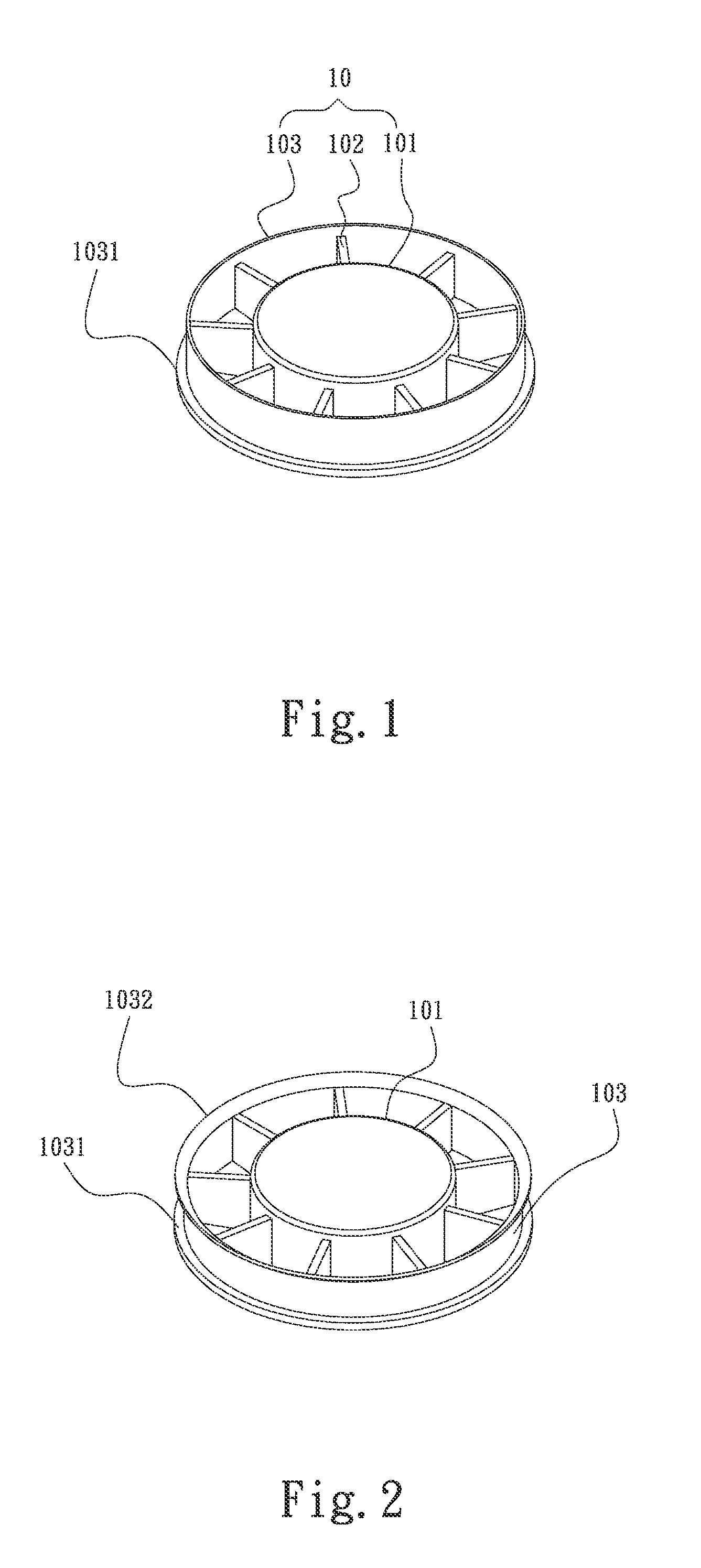
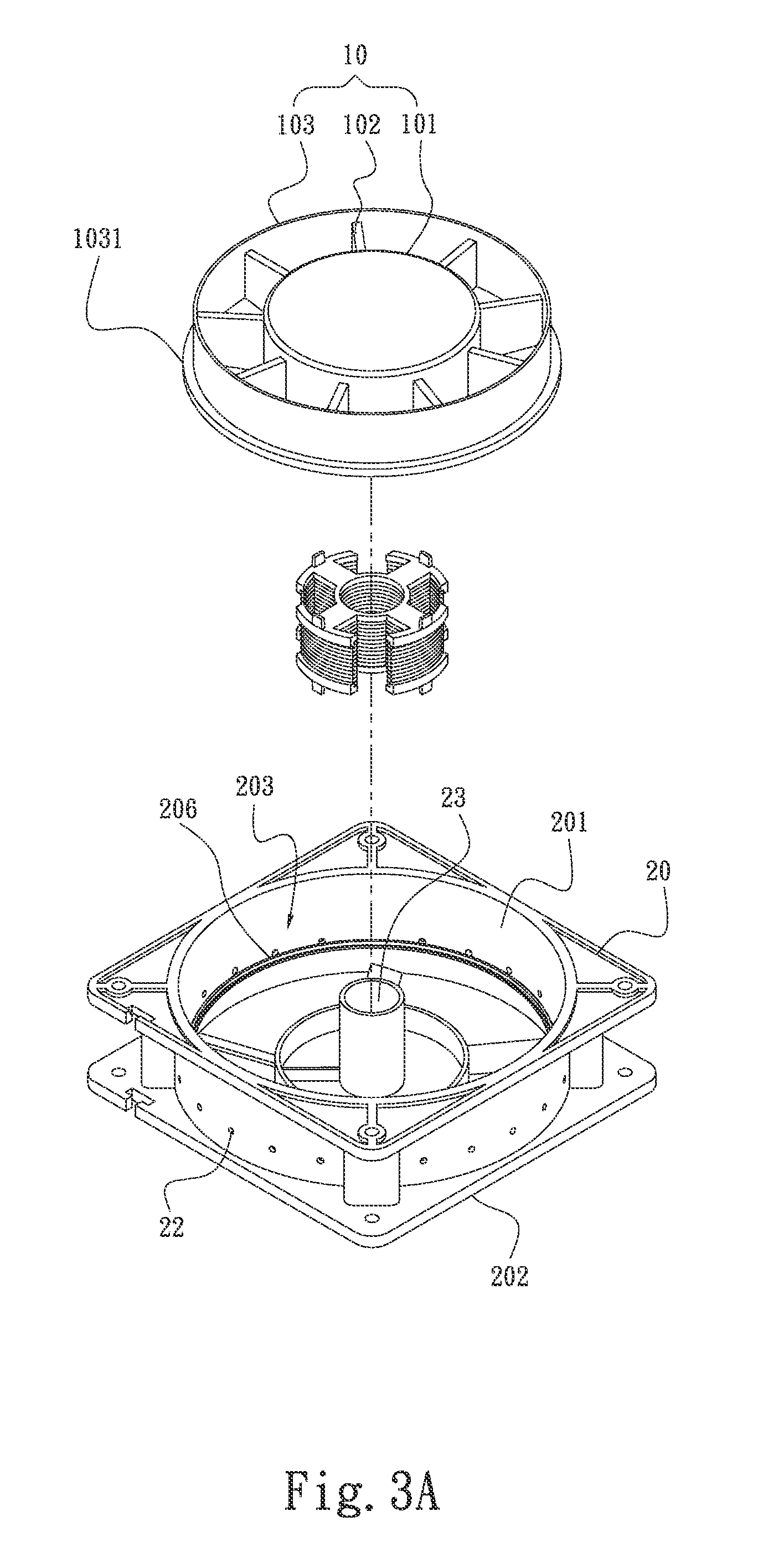
[0028]Please refer to FIG. 1 that is a perspective view of a first embodiment of an impeller structure for ring-type fan according to the present invention. As shown, the impeller structure for ring-type fan in the first embodiment thereof includes an impeller assembly 10 formed from a hub 101, a plurality of impellers 102 outward extended from and spaced around the hub 101, and a ring member 103 connected to radially outer ends of the impellers 102. The ring member 103 is formed around a rear outer circumferential edge with a stop section 1031. When a ring-type fan using the above-structured impeller structure operates, air flows through the impeller structure from a front side to a rear side thereof. Backflow...


PUM


Abstract

A ring-type fan includes a frame having a receiving space defined between an air inlet and an air outlet thereof and being provided along an inner side of the air outlet with an inward projected wall portion; an impeller assembly rotatably mounted in the receiving space and including spaced impellers outward extended from a hub, and a ring member connected to radially outer ends of the impellers and externally provided with a circle of stop section, which and the projected wall portion together define an air passage between them; and at least one pressure relief section defining an airflow guide on the frame to communicate with the receiving space and the air passage. Any backflow can be guided out of the frame via the air passage and the pressure relief section without interfering with the inflow of air, allowing the ring-type fan to have upgraded heat dissipation performance.

Description

FIELD OF THE INVENTION[0001]The present invention relates to a ring-type fan and an impeller structure thereof, and more particularly to a ring-type fan and an impeller structure thereof that can reduce the negative pressure at an air outlet of the fan caused by backflows of air and can therefore enable the ring-type fan to have upgraded heat dissipation performance.BACKGROUND OF THE INVENTION[0002]Following the quick technical development in the electronic industrial fields, various types of chips, such as the central processing unit (CPU), now have highly increased density of transistors provided thereon. While the currently available electronic devices have faster and faster data processing speed, they also consume more power and produce more heat during operation. The produced high amount of heat must be timely removed from the electronic devices, lest the raised temperature should cause burnout of the CPU and other electronic elements to adversely influence the whole system saf...

Claims


Application Information

Patent Timeline
Patent Type & Authority Patents(United States)
IPC IPC(8): F04D25/06F04D29/16F04D29/32
CPCF04D25/0613F04D29/164F04D29/326
Inventor LIU, WEN-HAO
Owner ASIA VITAL COMPONENTS SHENZHEN CO LTD
Why Eureka
Try Eureka