Method and system that provides an interactive debugging session

a debugging session and interactive technology, applied in error detection/correction, instruments, computing, etc., can solve problems such as errors that may occur within a program after its release, inconvenient debugging, and slow performan

Active Publication Date: 2016-01-12
INT BUSINESS MASCH CORP
View PDF14 Cites 3 Cited by
  • Summary
  • Abstract
  • Description
  • Claims
  • Application Information

AI Technical Summary

Problems solved by technology

Software applications may encounter errors (also called “bugs”) that lead to a number of problems, e.g., incorrect modification of data, system crashes, slower performance, etc.
However, errors may occur within a program after its release because of bugs that were not found beforehand.
Realistically, the process of debugging may continue well after the release of the program until the program no longer becomes useful or is improved upon.
Accordingly, the process of debugging can be a long an arduous task that often involves teams of programmers, especially with a larger software application.
If only one programmer at a time is allowed to make changes to the code, the efficiency of multiple programmers debugging is significantly, if not completely, hampered.
Current systems do not provide a seamless approach that allows multiple programmers to debug the same code at the same time.
A normal programmer does not usually have such a privilege and, therefore, wastes time attempting to obtain such an address change from someone who does have the privilege.
If a second user initiates another debugging session at the same time, the additional debugging session will not be successfully established because the I / O device is currently in use by the first user.
This may be inconvenient for the second user, who may want to utilize a different I / O device than the first user.
The utilization of additional infrastructure on a case-by-case basis is an inefficient approach because one programmer may have the resources for a particular infrastructure while another programmer may not have such resources.
As a result, current systems are not user friendly, which is an attribute that a debugger should ideally have to allow for easy navigation by programmers.

Method used


Image

  • Method and system that provides an interactive debugging session
  • Method and system that provides an interactive debugging session
  • Method and system that provides an interactive debugging session

Examples


Embodiment Construction

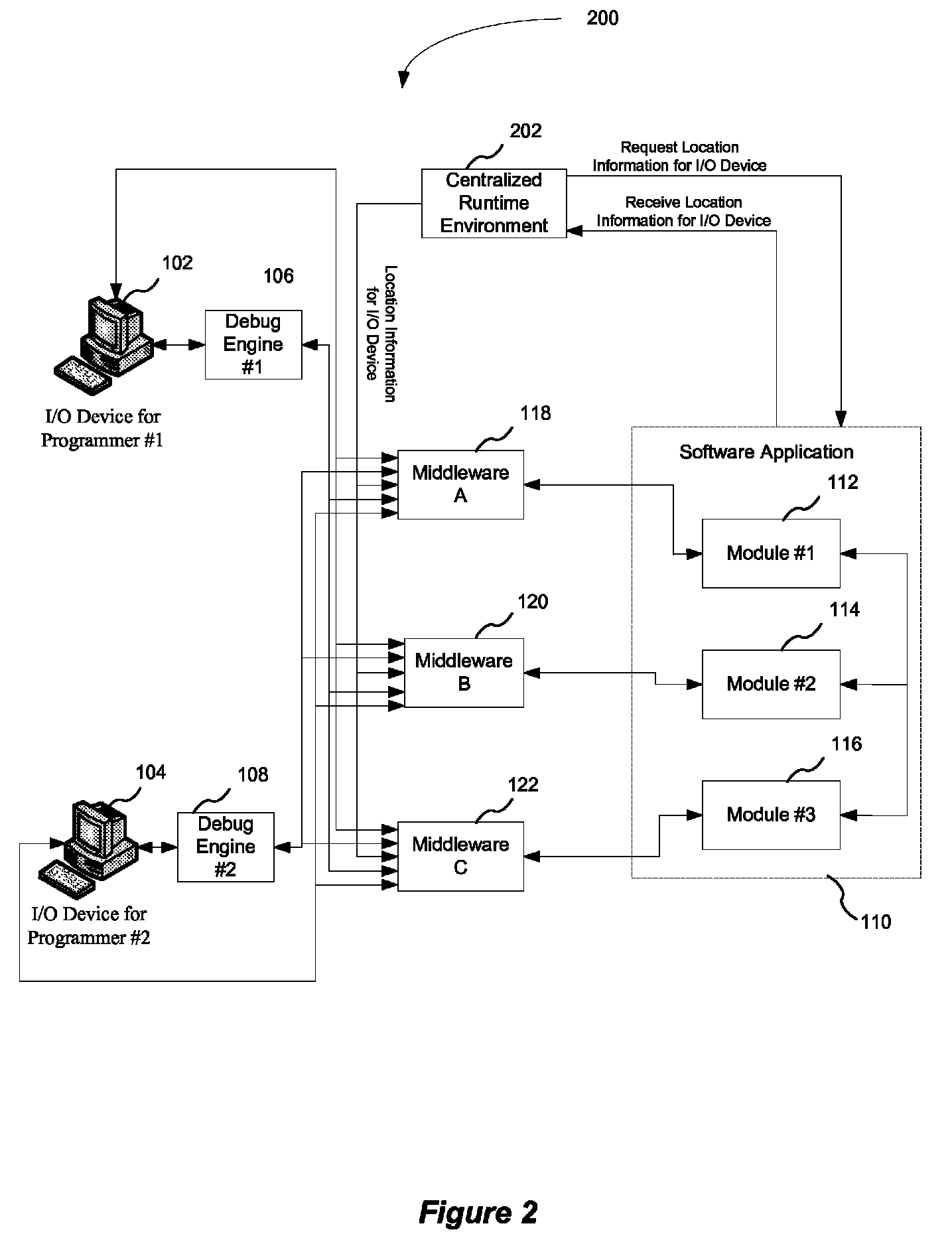
[0019]A centralized and consistent approach can be utilized by a debug engine to present an interactive debugging session. The approach provides a user friendly way for the programmer to specify an I / O device location for the I / O device that the programmer is utilizing to debug a program. Further, a list of programs to be debugged can be provided. In addition, other runtime conditions utilized in the debugging session can be provided. The I / O device location is provided to the debug engine, which can then initiate an interactive debugging session for the user at the I / O device that the programmer is utilizing.

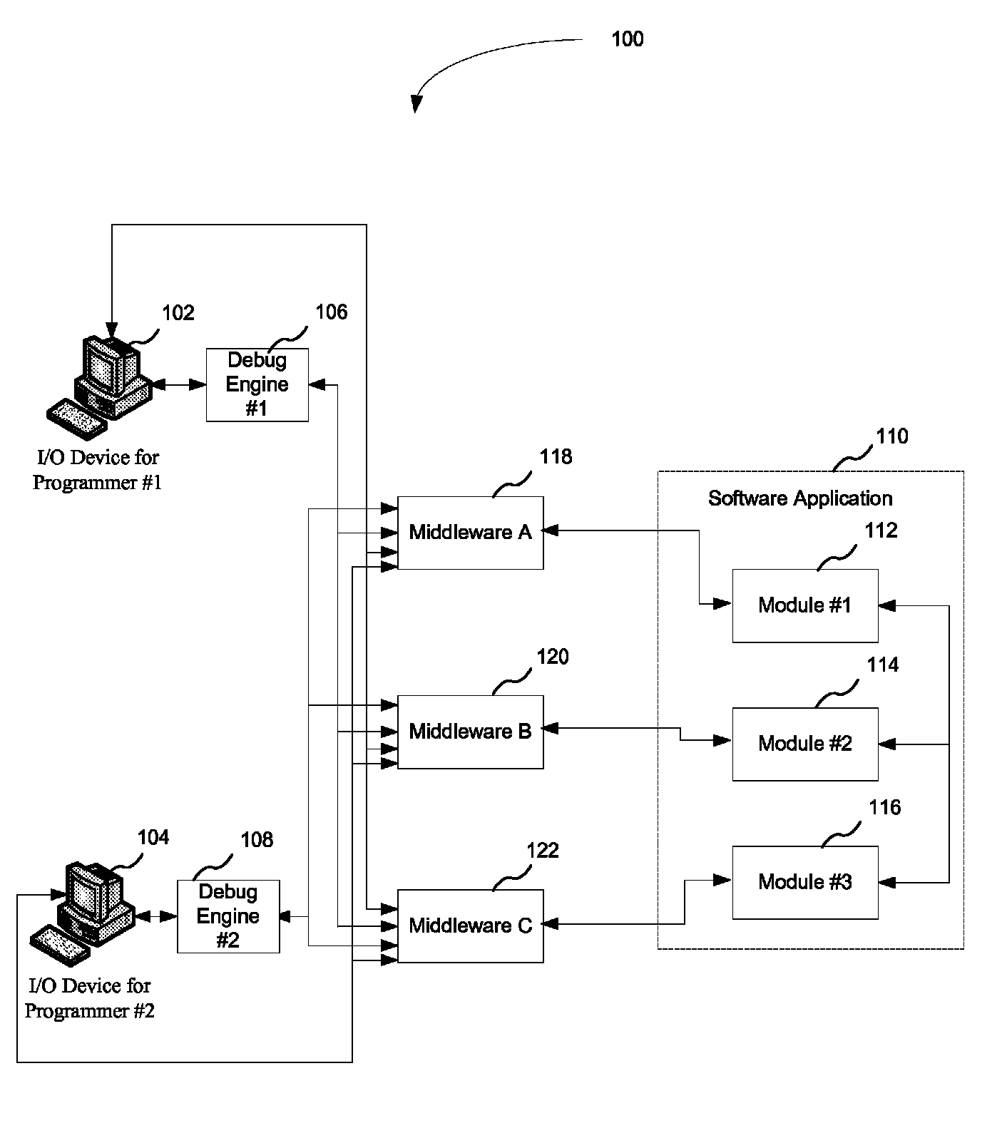
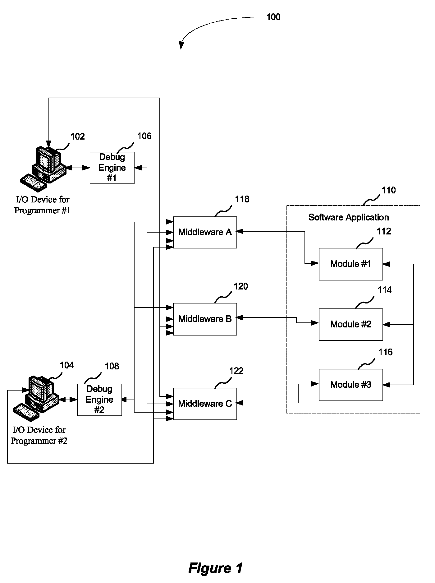
[0020]FIG. 1 illustrates a configuration 100 in which multiple programmers attempt to initiate debugging sessions to debug a software application 110 that is running (or executing) in a series of middleware components. In one embodiment, the software application 110 includes a plurality of modules, e.g., a first module 112, a second module 114, and a third module 116, that are ...


PUM


Abstract

A computer program product is disclosed. The computer program product includes a computer useable medium having a computer readable program. The computer readable program when executed on a computer causes the computer to receive user specific data for a debugging session. The user specific data includes a location for an input / output device. Further, the computer readable program when executed on the computer causes the computer to initiate a debugging session at the input / output device specified at the location in the user specific data.

Description

BACKGROUND[0001]1. Field[0002]This disclosure generally relates to testing software applications for errors. More particularly, the disclosure relates to an interactive debugging session.[0003]2. General Background[0004]Software applications may encounter errors (also called “bugs”) that lead to a number of problems, e.g., incorrect modification of data, system crashes, slower performance, etc. Software developers often attempt to discover as many bugs as possible during the development of the software application to eliminate the presence or at least minimize the number of bugs in the software application prior to release of the software application to the end user. A debugger is a software tool that a programmer utilizes to “debug” a program, i.e., find the bugs in a program. The debugger runs concurrently with the execution of the program and allows the programmer to monitor and control that execution. For instance, the programmer can monitor a particular variable or memory regis...

Claims


Application Information

Patent Timeline
Patent Type & Authority Patents(United States)
IPC IPC(8): G06F9/44G06F11/36
CPCG06F11/3656G06F11/36G06F11/362G06F11/3664
Inventor LIN, SHIHTAANAYA, FRANCISCO MIGUELVAN HECKE, WILFRIEDMANCHALA, VIKRAM
Owner INT BUSINESS MASCH CORP
Why Eureka
Try Eureka