Structure of connection between coaxial cable and shield terminal, and method of connection therebetween

a technology of shield terminal and coaxial cable, which is applied in the direction of permanent deformation connection, line/current collector details, electrical apparatus, etc., can solve the problems of complex assembly work, and achieve the effect of easy tightening of the outer peripheral surface, easy assembly work, and unnecessary peeling of the insulating

Active Publication Date: 2016-01-12
YAZAKI CORP
View PDF16 Cites 3 Cited by
  • Summary
  • Abstract
  • Description
  • Claims
  • Application Information

AI Technical Summary

Benefits of technology

[0015]In the structure of connection between the coaxial cable and the shield terminal according to the configuration (1), the end of the insulating tube is configured to have the inside diameter larger than the outside diameter of the press bond part, and the crimp member is arranged on the end of the insulating tube, and the press bond part is inserted between the inner peripheral surface of the end and the outer peripheral surface of the braided shield and is pressed and bonded to the outer peripheral surface of the braided shield by pressing and bonding the crimp member, so that it is unnecessary to peel the insulating tube so as to expose the braided shield in the size according to the press bond part of the shield terminal, with the result that assembly work can be facilitated.
[0016]In the structure of connection between the coaxial cable and the shield terminal according to the configuration (2), the crimp member is configured to have the seam orthogonal to the circumferential direction, so that the crimp member can easily tighten the outer peripheral surface of the insulating tube.
[0017]In the structure of connection between the coaxial cable and the shield terminal according to the configuration (3), the press bond part is formed in substantially the cylindrical shape without the seam, so that it is unnecessary to do work of folding a press bond piece, with the result that assembly work is facilitated.
[0018]The method of connection between the coaxial cable and the shield terminal according to the configuration (4) includes the press bond part insertion step of inserting the press bond part between the inner peripheral surface of the end of the insulating tube and the outer peripheral surface of the braided shield, and the press bond step of pressing and bonding the press bond part to the braided shield by pressing and bonding the ring-shaped crimp member arranged on the outer peripheral surface of the end of the insulating tube, so that it is unnecessary to peel the insulating tube according to the size of the press bond part, with the result that assembly work can be facilitated.

Problems solved by technology

In the structure of connection between the coaxial cable and the shield terminal described in JP-A-2009-99266, an insulating tube must be peeled so as to expose the braided shield in the size according to the press bond part of the shield terminal when the shield terminal is pressed and bonded to the braided shield, so that there was a problem that assembly work became complicated.

Method used


Image

  • Structure of connection between coaxial cable and shield terminal, and method of connection therebetween
  • Structure of connection between coaxial cable and shield terminal, and method of connection therebetween
  • Structure of connection between coaxial cable and shield terminal, and method of connection therebetween

Examples


embodiment

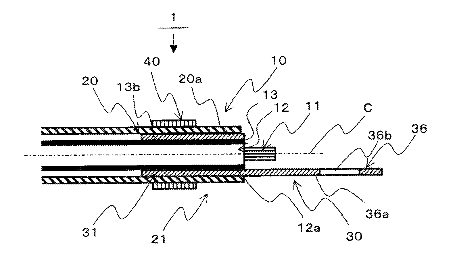
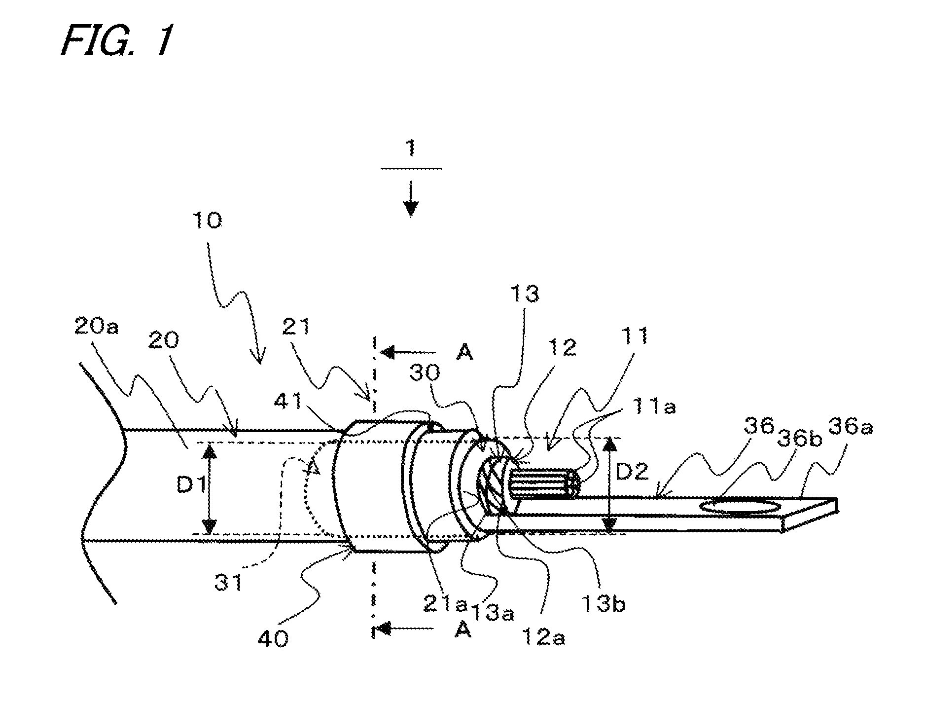
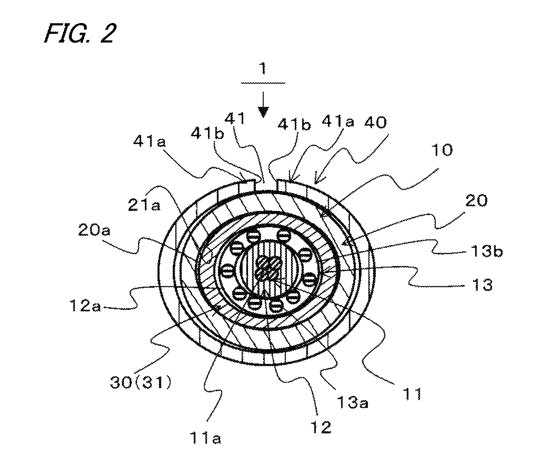
[0032]FIG. 1 is a perspective view showing a structure 1 of connection between a coaxial cable and a shield terminal according to an embodiment of the invention. FIG. 2 is a sectional view taken on line A-A of the structure 1 of connection between the coaxial cable and the shield terminal shown in FIG. 1. FIG. 3 is a perspective view showing the structure 1 of connection between the coaxial cable and the shield terminal before a crimp member 40 is attached. FIG. 4 is a sectional view taken on line B-B of the structure 1 of connection between the coaxial cable and the shield terminal before the crimp member 40 shown in FIG. 3 is attached. FIG. 5 is an enlarged perspective view of a shield terminal 30 shown in FIG. 1. FIGS. 6A and 6B are explanatory diagrams of a positional relation between a press bond part 31 and a braided shield 13 and its effect.

[0033]The structure 1 of connection between the coaxial cable and the shield terminal according to the embodiment of the invention is con...

modified example 1

[0061]Next, a modified example 1 of the structure 1 of connection between the coaxial cable and the shield terminal according to the embodiment of the invention will be described using FIG. 8. FIG. 8 is a perspective view showing a structure 2 of connection between a coaxial cable and a shield terminal of the modified example 1.

[0062]The structure 2 of connection between the coaxial cable and the shield terminal of this modified example 1 differs from the structure 1 of connection between the coaxial cable and the shield terminal of the embodiment in that the structure 2 is configured to have an insulating tube 22 instead of the insulating tube 20.

[0063]In addition, the other configuration is similar to that of the embodiment, and the same numerals are assigned to the same components as those of the embodiment.

[0064]Except for an end 21 of the insulating tube 22, an inside diameter D2 is set smaller than the end 21 so as to cover a braided shield 13 without any gap.

[0065]The structu...

modified example 2

[0066]Next, a modified example 2 of the structure 1 of connection between the coaxial cable and the shield terminal according to the embodiment of the invention will be described using FIGS. 9 and 10. FIG. 9 is a perspective view showing a structure 3 of connection between a coaxial cable and a shield terminal of the modified example 2. FIG. 10 is a sectional view taken on line C-C of the structure 3 of connection between the coaxial cable and the shield terminal shown in FIG. 9.

[0067]The structure 3 of connection between the coaxial cable and the shield terminal of this modified example 2 differs from the structure 1 of connection between the coaxial cable and the shield terminal of the embodiment in that the structure 3 is configured to have a shield terminal 32 instead of the shield terminal 30.

[0068]In addition, the other configuration is similar to that of the embodiment, and the same numerals are assigned to the same components as those of the embodiment.

[0069]A press bond par...


PUM


Abstract

A structure of connection between a coaxial cable and a shield terminal includes the coaxial cable configured to have at least one core wire part made of a conductor, an insulating coating part with which said core wire part is coated, a braided shield with which an outer peripheral surface of said insulating coating part is covered, and an insulating tube with which an outer peripheral surface of said braided shield is covered, the shield terminal that has a cylindrical press bond part pressed and is bonded to the outer peripheral surface of the braided shield, and a ring-shaped crimp member that is pressed and bonded to an outer peripheral surface of the insulating tube.

Description

CROSS REFERENCE TO RELATED APPLICATIONS[0001]This application is a continuation of PCT application No. PCT / JP2012 / 073390, which was filed on Sep. 6, 2012 based on Japanese Patent Application (No. 2011-198136) filed on Sep. 12, 2011, the contents of which are incorporated herein by reference.BACKGROUND OF THE INVENTION[0002]1. Field of the Invention[0003]The present invention relates to a structure of connection between a coaxial cable and a shield terminal, and a method of connection therebetween.[0004]2. Description of the Related Art[0005]A coaxial cable used as an antenna wire etc. is conventionally constructed so that in order to block noise of electromagnetic waves etc. from the outside, a core wire part made of a conductor covered with an insulating coating is covered with a braided shield and an outer peripheral surface of this braided shield is covered with an insulating tube. In such a coaxial cable, a shield terminal is connected to the braided shield in order to make eart...

Claims


Application Information

Patent Timeline
Patent Type & Authority Patents(United States)
IPC IPC(8): H01R4/18H01R4/20H01R9/05H01R43/048
CPCH01R4/183H01R4/20H01R9/0518H01R43/048
Inventor MATSUSHITA, KOUICHIRO
Owner YAZAKI CORP
Why Eureka
Try Eureka