3D laser measuring device

a laser measuring device and 3d technology, applied in the field of measurement technology, can solve the problems of wasting time and energy, and the measurement of the three dimensions of the shipping box would be much more inconvenient, and achieve the effect of saving energy and being convenient and efficien

Inactive Publication Date: 2016-01-19
LIN ZHONG JIAN
View PDF12 Cites 9 Cited by
  • Summary
  • Abstract
  • Description
  • Claims
  • Application Information

AI Technical Summary

Benefits of technology

[0003]Aiming at solving the above-mentioned problem, the present invention provides a 3D laser measuring device, which may measure three dimensions of a shipping box and can be easily operated.
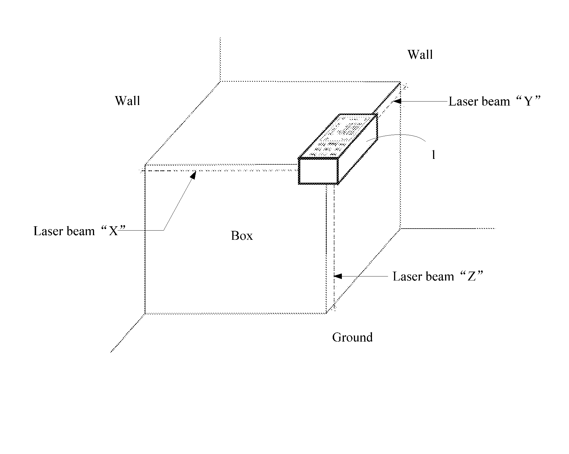
[0019]The 3D laser volume measurer of the present invention takes only the click of one measurement button to measure the three dimensions of the box simultaneously, and it is easy and efficient. When using the laser reflecting corner plates, the three dimensions of the box can be measured at any position, without the need of placing the box against a wall corner. When measuring the three dimensions of a shipping box, there is no need to move the shipping box and just placing the 3D laser measurer onto the shipping box may obtain the three dimensions of the box. Compared to the existing measuring devices, it is easy and convenient, and furthermore is time-saving and energy-saving.

Problems solved by technology

The existing measuring devices are generally large-scale devices, and it is required to place a shipping box onto the bearing platform of the measuring device when measuring, causing waste of time and energy.
Moreover, if the volume of the box is too large and the weight of the box is too heavy, measuring the three dimensions of the shipping box would be much more inconvenient.

Method used


Image

  • 3D laser measuring device
  • 3D laser measuring device
  • 3D laser measuring device

Examples


Embodiment Construction

[0025]The embodiments of the present invention will be detailed in the following in conjunction with the accompanying drawings.

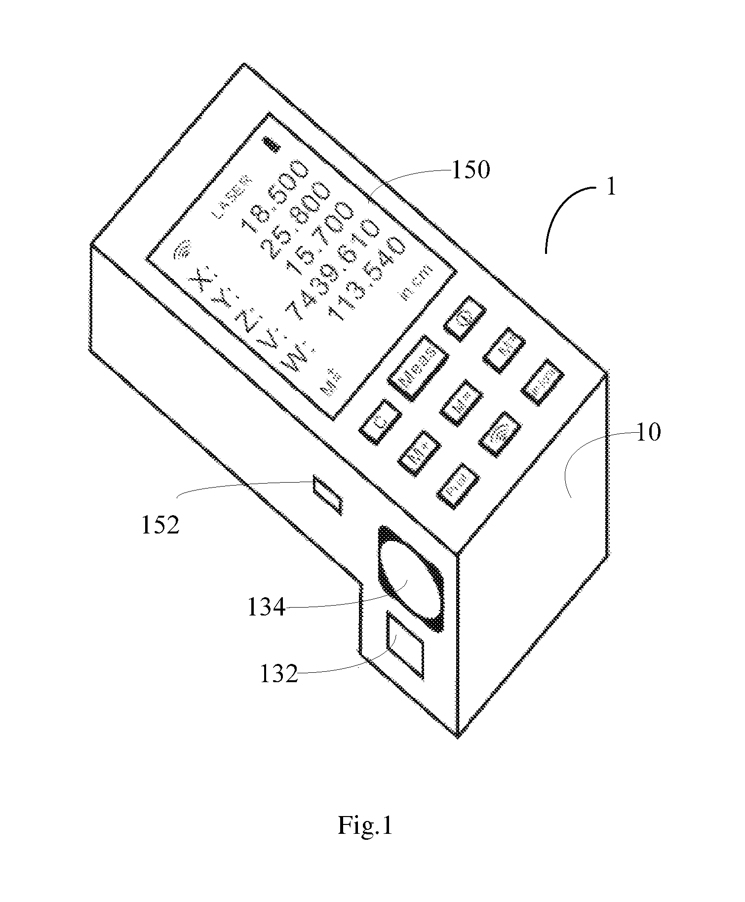
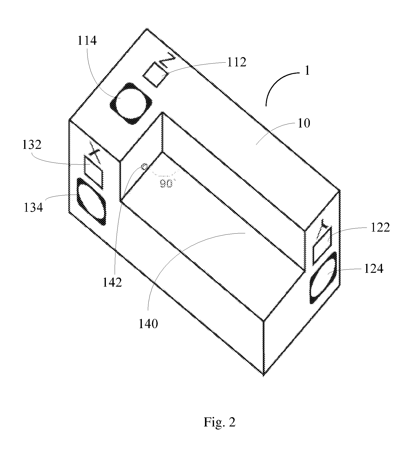
[0026]FIG. 1 illustrates a perspective view of a 3D laser measurer according to the embodiments of the present invention. FIG. 2 is a perspective view of the 3D laser measurer of FIG. 1 observed from a different point of view. Referring to FIG. 1 and FIG. 2, the 3D laser measurer 1 includes a measurement body 10. A Z-axial laser beam outlet 112 and a Z-axial reception lens 114, which are used for measuring the height, are arranged on the bottom of the measurement body 10. A Y-axial laser beam outlet 122 and a Y-axial reception lens 124, which are used for measuring the width, are arranged on one side wall of the measurement body 10, and the X-axial laser beam outlet 132 and an X-axial reception lens 134, which are used for measuring the length, are arranged on the other side wall of the measurement body 10. A groove (or rectangular indent) 140 is formed in t...


PUM


Abstract

The invention discloses a portable and movable 3D laser measuring device, comprising: a measurement body; an X-axial laser beam outlet and an X-axial reception lens arranged on a side wall of the measurement body, and a Y-axial laser beam outlet and a Y-axial reception lens arranged on another side wall; a Z-axial laser beam outlet and a Z-axial reception lens arranged on the bottom of the measurement body, and a groove formed in the bottom and being open at the side wall with the X-axial laser beam outlet and at the side wall with the Y-axial laser beam outlet; a control device placed inside the measurement body and configured to control the emitting of the laser beams from the laser beam outlets when receiving a measurement instruction through a measurement button on the measurement body. By using the 3D laser measuring device, the three dimensions of a shipping box can be easily measured.

Description

FIELD OF THE INVENTION[0001]The present invention relates to the field of measurement technology, more particularly, to a portable and movable 3D laser measuring device.BACKGROUND OF THE INVENTION[0002]In the course of cargo transportation, it is generally required to use a shipping box for shipping the cargo. When using transportation tools to ship a large quantity of goods, it is critical for the carriage to obtain the volume and weight of shipping boxes in advance. The existing measuring devices are generally large-scale devices, and it is required to place a shipping box onto the bearing platform of the measuring device when measuring, causing waste of time and energy. Moreover, if the volume of the box is too large and the weight of the box is too heavy, measuring the three dimensions of the shipping box would be much more inconvenient.SUMMARY OF THE INVENTION[0003]Aiming at solving the above-mentioned problem, the present invention provides a 3D laser measuring device, which m...

Claims


Application Information

Patent Timeline
Patent Type & Authority Patents(United States)
IPC IPC(8): G01B11/00G01C15/00G01B9/00G02B5/12
CPCG01B11/002G01B9/00G01C15/002G02B5/12G01B11/00G01B11/02G01B11/026G01S17/08G01S17/87G01S17/88G01S7/4808G01S7/4813G02B5/124
Inventor LIN, ZHONG, JIAN
Owner LIN ZHONG JIAN
Why Eureka
Try Eureka