Acoustic inhaler flow measurement

a technology of inhaler flow and measurement method, which is applied in the direction of liquid/fluent solid measurement, inhalator, medical device, etc., can solve the problems of flow path within the inhaler creating a characteristic flow noise sound, mechanical design of the inhaler, and not meeting the demands

Active Publication Date: 2016-01-26
BANG & OLUFSEN MEDICOM
View PDF12 Cites 32 Cited by
  • Summary
  • Abstract
  • Description
  • Claims
  • Application Information

AI Technical Summary

Benefits of technology

[0005]It is an object of the present invention to provide a simple add-on electronic monitoring device to be attached to an existing conventional inhaler design without the need of changing the design and risk of changing the aerodynamic behaviour of the inhaler flow path. The monitoring device may contain acoustic sensors, detectors, control circuit, data transmission circuit, battery, display or diodes and optional circuits for indirectly detecting dose loading in the inhaler.
[0024]In order to be able to cancel out ambient noise or handling noise, In one situation, the sensor further comprises another acoustic sensor for measurement of, and in communication with the surroundings. Thus, the signal from this other sensor may be used for eliminating ambient noise or handling noise from the signal from the actual sensor.
[0025]In another situation, the sensor comprises an ambient noise reducing acoustic sensor design, where the front of the sensor is brought into direct contact with the exterior surface of the inhaler, and where the rear side of the sensor Is in direct acoustic communication with the surroundings via a port in a casing enclosing the sensor, thereby cancelling ambient noise directly in the sensor.
[0034]The optimum position of the sensor will depend on the construction of the inhaler and the materials of which it is made. The vibrations caused by flow in the flow channel will travel through all materials but with different efficiency depending on the actual material and the construction of the inhaler. Presently, it is preferred to position the sensor in contact with a surface part which is allowed to and adapted to vibrate with a frequency in the interval of 100-3000 Hz in that the vibration of this part during a flow will amplify the sound or vibration sensed by the sensor.

Problems solved by technology

U.S. Pat. No. 5,505,195 describes an electronic device to be attached to a standard dry powder inhaler, but the description reveals that the flow sensors disclosed interfere with the mechanical design of the inhaler and will therefore not conform to the demands above.
GB-2262452 discloses several techniques for flow measurements within inhalers, but they all measure the flow inside the inhaler flow path and will therefore not conform to the above requirements.
When a user inhales the medication, the flow path within the Inhaler creates a characteristic flow noise sound depending on flow rate and turbulences.

Method used


Image

  • Acoustic inhaler flow measurement
  • Acoustic inhaler flow measurement
  • Acoustic inhaler flow measurement

Examples


first embodiment

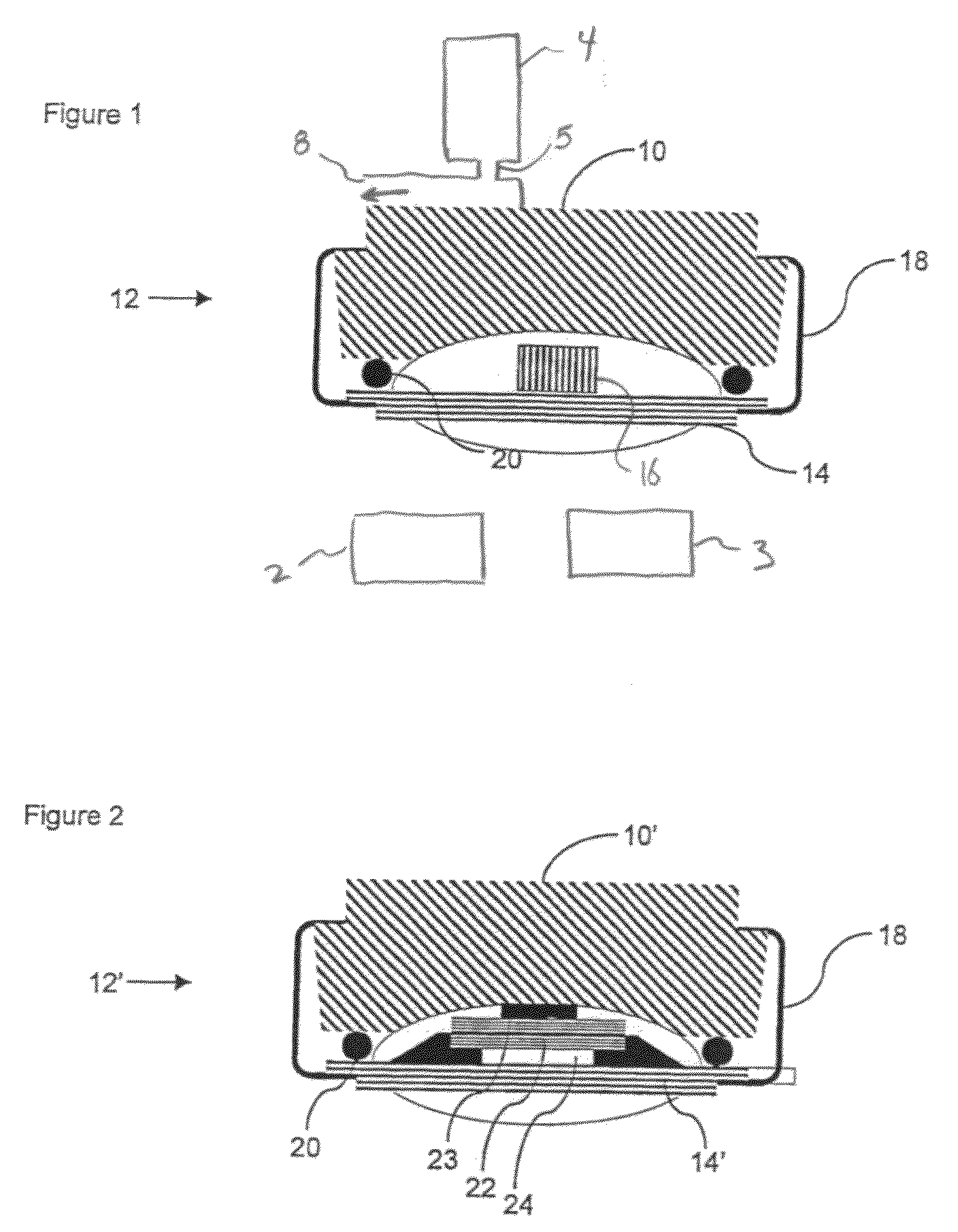
[0048]FIG. 1 illustrates a cross section through an inhaler 10, which may be any Inhaler, such as the Diskus® (GSK), Technohaler® (Innovata Biomed), D2L® (Ivax), Turbuhaler® (AstraZeneca), SkyeHaler DPI® (SkyePharma), Easi-Breathe DPI® (IVAX), Pulvinal® (Chiesi), EasyHaler® (Orion Farmos), Clickhaler® (Innovata Biomed), Taifun® (Focus Inhale), or the Ultrahaler® (Aventis). At the bottom (or at any other suitable position), a sensor assembly 12 is provided which comprises an element 14 holding a microphone 16 and which is fastened via a fastening clip 18 to the bottom of the inhaler 10. Between the element 14 and the bottom, a resilient element 20 is provided for sealing airborne noise from the surroundings away from the microphone 16. The inhaler 10 may have a dispenser / container 4 for outputting medication at a dispensing position 5 from which the medication flows through a gas outlet 8. The sensor assembly 12 may further include a processor 2 and a display 3.

[0049]The space define...

second embodiment

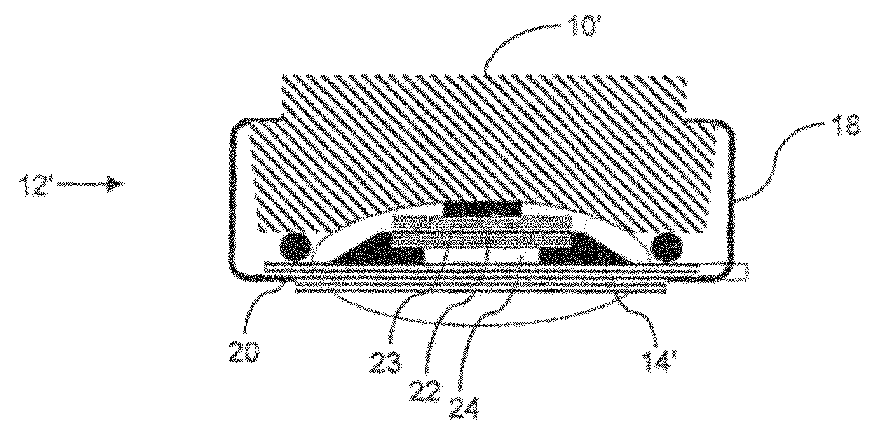
[0051]FIG. 2 illustrates a cross section through an inhaler 10′ having a sensor 12′ as seen in EP-A-1480555, “A transducer for bio-acoustic signals”, which discloses a contact sensor 16′ with a front side 23 and a rear side 22, the front side 23 being in solid communication with the source of sound (in this application the inhaler) and the rear side 22 being in communication with the surroundings through a port 24 in the sensor cover 14′, said port 24 and cover 14′ constituting an acoustic impedance that can optimize the ambient noise cancelling within the sensor 12′.

[0052]In general, the sensor 12 / 12′ may be attached to the inhaler by the clip 18 and be removed there from such as to be attached to another dispenser 10 / 10′. It is also seen that the operation of the sensor 12 / 12′ makes no impact on the flow path defined within the dispenser 10 / 10′.

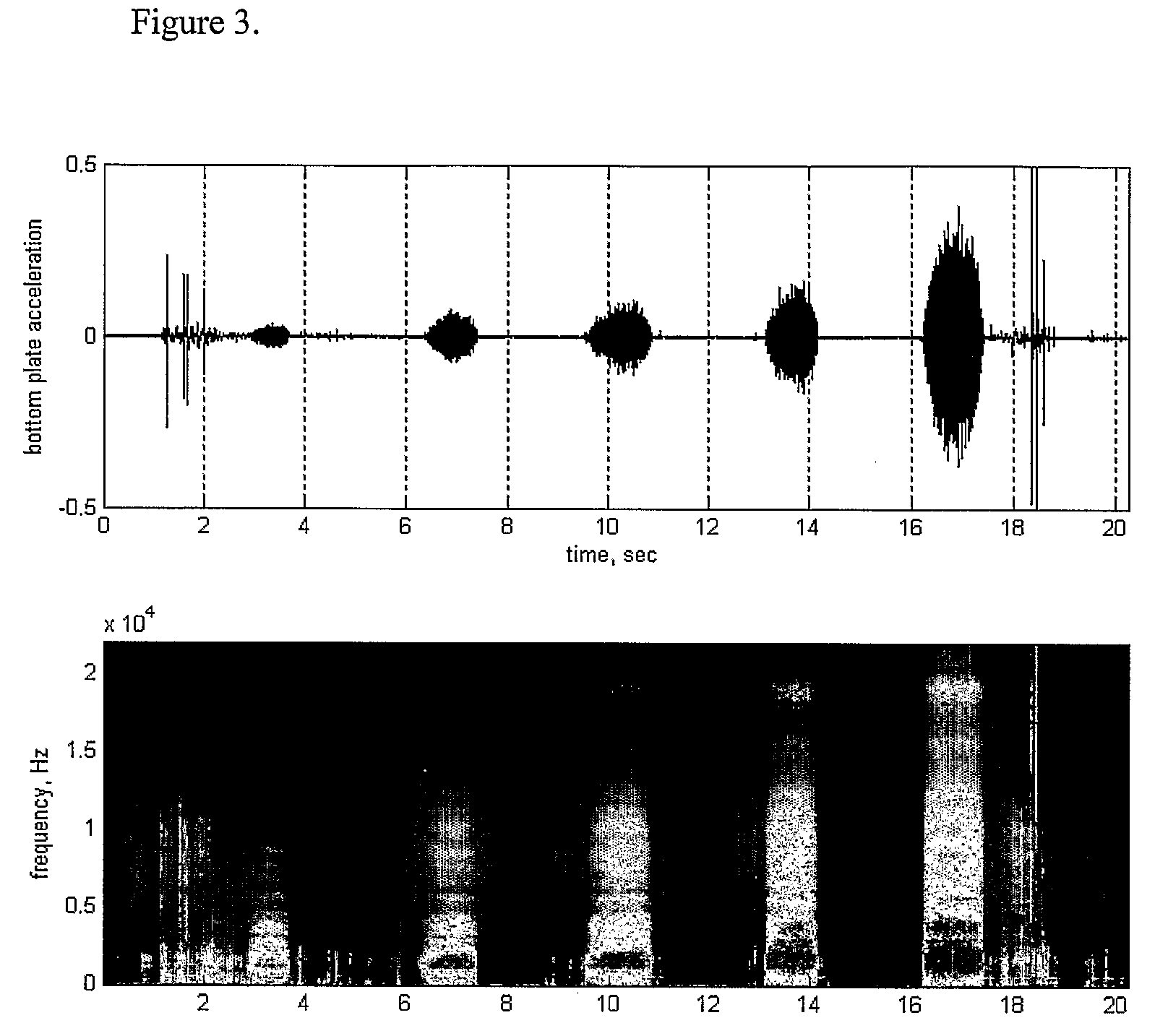
[0053]The detected or sensed sound / vibration spectrum varies with the flow rate in the inhaler. In FIG. 3, results of experiments illustra...


PUM


Abstract

A dry powder or aerosol inhaler having attached thereto, in a detachable manner, a sound / vibration sensor adapted to sense sound / vibration in the interval of 100-3000 Hz and there from derive a parameter of a flow in a flow path of the inhaler. The sensor does not interfere with the flow path of the inhaler.

Description

FIELD OF THE INVENTION[0001]The present invention relates to the field of analyzing, monitoring, logging and transmitting information on inhaler-based medication history. Such information may be used for clinical trials, where the use pattern versus prescription of an inhaler based drug is an important parameter, or the information feedback may be displayed directly to the user to guide the user to better inhalation and compliance.[0002]More specifically this invention relates to a device, which may be attached to an existing inhaler without any need of intervention within the function of the inhaler. The inhalation flow is measured acoustically outside the inhaler by means of a microphone or similar acoustic / vibration sensor. Additionally, means for measuring dose loading externally from the device will be disclosed.BACKGROUND OF THE INVENTION[0003]Inhalers have become wide spread for treating i. e. respiratory disorders, diabetes, osteoporosis and pain. The inhaler devices are cli...

Claims


Application Information

Patent Timeline
Patent Type & Authority Patents(United States)
IPC IPC(8): A61M15/00G01F1/66A61M16/00
CPCA61M15/0065A61M15/00A61M2016/0039A61M2202/064A61M2205/3375G01F1/666A61M15/008
Inventor ANDERSEN, BJORN KNUDPOULSEN, SVEND-ERIK
Owner BANG & OLUFSEN MEDICOM
Why Eureka
Try Eureka