Toroidal roller bearing

a technology of roller bearings and bearings, which is applied in the direction of roller bearings, mechanical equipment, rotary machine parts, etc., can solve the problems of rolling bearing slippage, reduced service life, and increased bearing friction

Active Publication Date: 2016-01-26
AB SKF
View PDF6 Cites 1 Cited by
  • Summary
  • Abstract
  • Description
  • Claims
  • Application Information

AI Technical Summary

Benefits of technology

[0010]Due to this design, the rollers will be axially guided and keep the rollers in position in their loaded and unloaded zone during operation of the bearing. It has been found by the inventors that when size and thus the weight of the roller elements is large, it is especially advantageous to guide the roller elements axially by the cage against one of the bearing rings. Especially if the bearing is mounted on a non-horizontal shaft or in circumstances when the roller elements are exposed of axial forces there has been found to be a need for guiding the roller elements in a way keeping them in position both when being in a loaded and unloaded condition. In an alternative embodiment, a separate element, such as a ring, may be used as a corresponding guiding element for the cage. The ring may for instance be positioned axially outside the bearing.
[0017]In an embodiment of the toroidal roller bearing, the surface has a friction coefficient below 0.20 to allow a smooth sliding contact between the means and the surface. The surface may obtain a low friction coefficient by e.g. providing a smooth surface roughness on a steel surface or by providing a low-friction coating on the surface.

Problems solved by technology

The rollers, when in an unloaded zone, may for instance be braked by the cage, which will lead to roller slip.
This may lead to a reduction in the service life.
Another effect that may arise for the rollers in its unloaded zone is roller skew, caused by e.g. the cage, which may lead to increased friction in the bearing, increased unwanted forces on the cage or increased wear of the bearing components.
This may lead to noise and damages on the surfaces of the rollers and the raceways.

Method used


Image

  • Toroidal roller bearing
  • Toroidal roller bearing
  • Toroidal roller bearing

Examples


Embodiment Construction

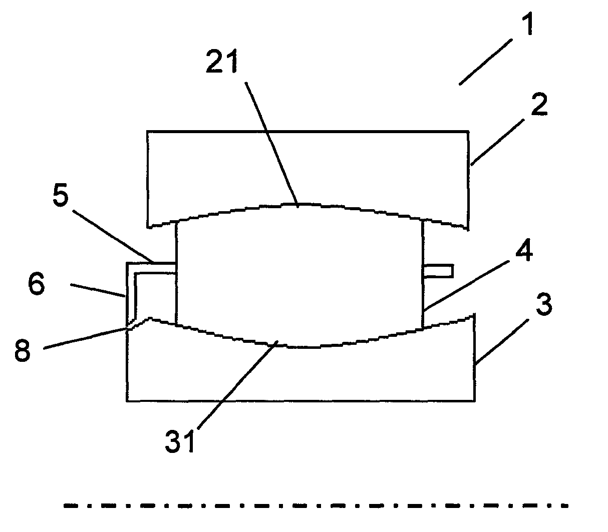
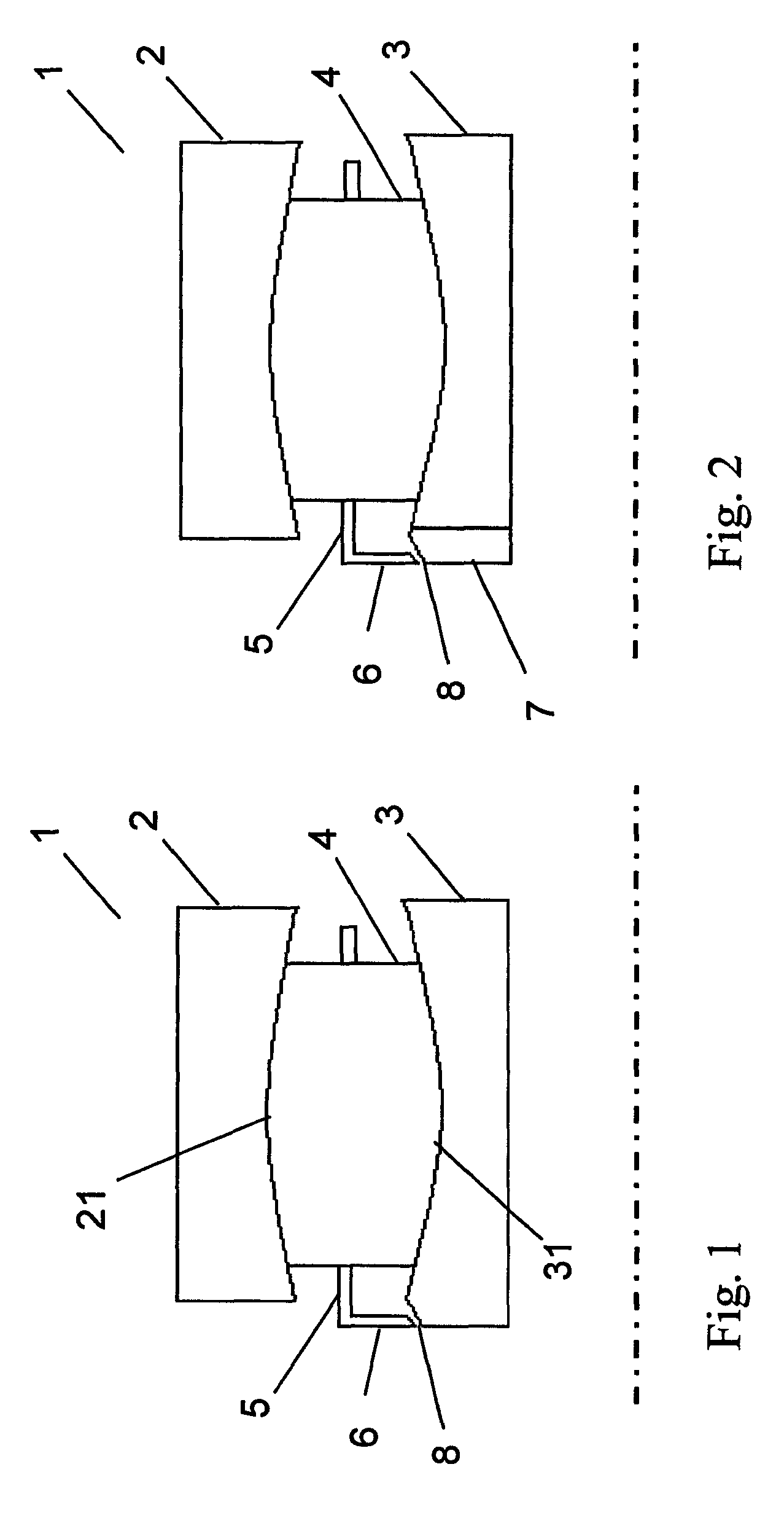
[0027]In FIG. 1, an axial cross section of a toroidal roller bearing 1 according to the invention is disclosed. The cross section is a cross section of a plane, wherein the axial line of the bearing 1 is in the plane. The toroidal roller bearing 1 comprises an outer ring 2, an inner ring 3, a plurality of roller elements 4 and a cage 5. The toroidal roller bearing 1 allows for axial and angular displacement of the outer ring 2 relative the inner ring 3. This is possible due to the configuration of the rings 2, 3 and the roller elements 4. The inner ring 3 and the outer ring 2 present concave raceways 31 and 21 respectively, and the roller elements 4 present corresponding convex shapes. The curve radii of the raceways 21, 31 and the roller elements 4 are substantially greater than the greatest distance between the central axes and the surfaces 21 and 31 of the raceways. The cage 5 has a number of roller pockets (not shown) where the rollers 4 are located in order to separate the roll...


PUM


Abstract

A toroidal roller bearing, which comprises an outer ring, an inner ring and a plurality of roller elements interposed between the outer and inner rings, wherein the toroidal roller bearing allows for angular and axial displacement between the outer ring and the inner ring. The bearing includes a cage for holding the roller elements, wherein the cage provides an axial guiding feature for axially guiding the roller elements against at least one of the outer ring, inner ring and a separate element located outside the toroidal roller bearing.

Description

CROSS REFERENCE TO RELATED APPLICATIONS[0001]This is a National Stage application claiming the benefit of International Application Number PCT / SE2013 / 000054, filed on 17 Apr. 2013 (Apr. 17, 2013), which claims priority to Sweden Patent Application 1200242-4, filed on 24 Apr. 2012 (Apr. 24, 2012), both of which are is incorporated herein by reference in their entireties.FIELD OF THE INVENTION[0002]The invention relates to a toroidal roller bearing. Toroidal roller bearings are known for its ability to allow both axial and angular displacement of its bearing rings.[0003]According to a first aspect, the invention regards a toroidal roller bearing.[0004]According to a second aspect, the invention regards a bearing arrangement comprising a toroidal roller bearing and a shaft onto which the bearing is mounted.BACKGROUND OF THE INVENTION[0005]Toroidal roller bearings are known and have been used for many years due to its ability to allow for both axial and angular relative displacement bet...

Claims


Application Information

Patent Timeline
Patent Type & Authority Patents(United States)
IPC IPC(8): F16C23/08F16C33/58F16C33/36F16C33/46F16C19/26F16C19/22
CPCF16C33/4605F16C19/22F16C19/26F16C23/086F16C33/586F16C2202/02F16C23/08F16C2360/31
Inventor WENDEBERG, HANSEFRAIMSSON, LINUS
Owner AB SKF
Why Eureka
Try Eureka