Arrangement comprising a circuit breaker unit

a circuit breaker and arrangement technology, applied in the direction of air-break switches, high-tension/heavy-dress switches, electrical apparatuses, etc., can solve the problems of excessive temperature of switching gas, deformation of circuit breaker units, and increased volum

Active Publication Date: 2016-02-02
SIEMENS ENERGY GLOBAL GMBH & CO KG
View PDF20 Cites 3 Cited by
  • Summary
  • Abstract
  • Description
  • Claims
  • Application Information

AI Technical Summary

Benefits of technology

[0021]The arrangement of a circuit breaker unit within an encapsulating housing makes it possible to form the encapsulating housing in a fluid-tight manner, such that an electrically insulating fluid flushing over or flushing through the circuit breaker unit is encapsulated and a sporadic volatilization of said electrically insulating fluid is suppressed to the greatest possible extent. The encapsulating housing thus constitutes a barrier for the electrically insulating fluid and may also be formed as a pressure-resistant encapsulating housing, such that electrically insulating fluid enclosed within the encapsulating housing can also be acted on by a pressure that is increased with respect to the environment surrounding the encapsulating housing. The encapsulating housing surrounds the circuit breaker unit, wherein the interior of the encapsulating housing defines the environment surrounding the circuit breaker unit. The switching gas channel, which connects the breaker gap to an environment surrounding the circuit breaker unit thus constitutes a connection between the breaker gap and the interior of the hermetically sealed-off encapsulating housing via the switching gas channel and the switching gas outlet opening. It is thus possible to allow switching gas to discharge relatively quickly from the interior of the circuit breaker unit into the environment surrounding the circuit breaker unit and to already cool the switching gas in a preliminary manner in this way, such that a further swirling, mixing and cooling of the switching gas, which is already pre-cooled, with the electrically insulating fluid located within the encapsulating housing can take place outside the circuit breaker unit within the encapsulating housing.

Problems solved by technology

In the absence of such a switching gas channel, a generation of switching gas in the breaker gap could lead to an undesirable pressure increase, which could ultimately lead to a destruction of the circuit breaker unit.
The temperature of the switching gas is usually increased excessively and also experiences an increase in volume due to the excessive increase in temperature.

Method used


Image

  • Arrangement comprising a circuit breaker unit

Examples


Embodiment Construction

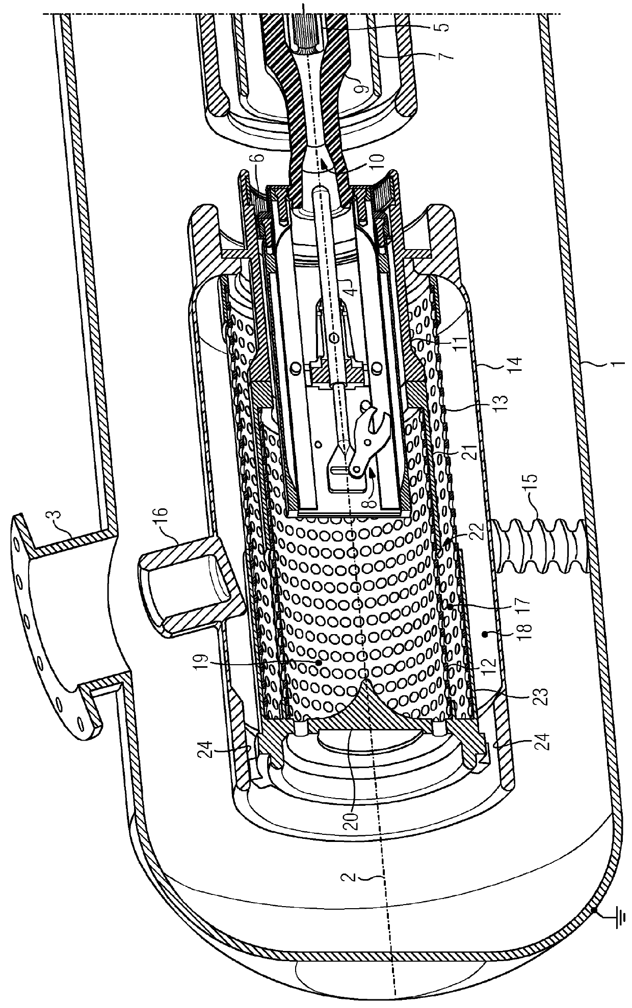
[0025]The FIGURE shows a partly cut-away arrangement comprising a circuit breaker unit which is arranged within an encapsulating housing 1. The encapsulating housing 1 in the present case has a metal cast body, which carries ground potential. The interior of the encapsulating housing 1 is filled with an electrically insulating fluid, preferably an electrically insulating gas, such as sulfur hexafluoride or nitrogen or a mixture with the gases. The electrically insulating fluid is exposed here to overpressure. Due to the design of the encapsulating housing 1, which allows said housing to be sealed off hermetically, a sporadic volatilization of the electrically insulating fluid at overpressure is only possible with difficulty.

[0026]The encapsulating housing 1 extends substantially in a tubular manner coaxially with a longitudinal axis 2, wherein the end sides of the encapsulating housing 1 are closed by cap-like closure elements. The longitudinal axis 2 defines an axial direction. Fur...


PUM


Abstract

A circuit breaker unit has first and second arcing contact pieces. A breaker gap is formed between the two arcing contact pieces. A switching gas channel leads to the breaker gap and guides the switching gas to a switching gas outlet opening of the circuit breaker unit. The switching gas channel is formed with first and second pipe sections that overlap each other at least in sections and have discharge openings in their cover surfaces. Continuous discharge openings in the first and in the second pipe sections are axially offset in relation to each other.

Description

BACKGROUND OF THE INVENTIONField of the Invention[0001]The invention relates to an arrangement comprising a circuit breaker unit having a breaker gap arranged between a first and a second arcing contact piece and having a switching gas channel, which leads on the one hand to the breaker gap and on the other hand to a switching gas outlet opening of the circuit breaker unit and which is delimited, at least in portions, by a first and a second pipe section, which overlap one another in the axial direction in an overlap segment and each have discharge openings in their lateral surfaces.[0002]An arrangement of this type is known for example from the German utility model DE 1 889 068. There, a circuit breaker unit in the form of a pipe quenching chamber is described, which has a breaker gap between arcing contact pieces. In order to allow switching gas generated in the breaker gap to escape outwardly, the arrangement there is equipped with a switching gas channel which leads on the one h...

Claims


Application Information

Patent Timeline
Patent Type & Authority Patents(United States)
IPC IPC(8): H01H33/70H01H33/58
CPCH01H33/7015H01H33/58
Inventor CERNAT, RADU-MARIANLEHMANN, VOLKERNOWAKOWSKI, ANDRZEJ
Owner SIEMENS ENERGY GLOBAL GMBH & CO KG
Why Eureka
Try Eureka