
Trigger assembly

a technology of trigger assembly and trigger, which is applied in the direction of firing/triggering mechanisms, weapons, weapon components, etc., can solve the problems of firearms, etc., and achieve the effects of easy adaptation, low internal friction, and increased precision

Inactive Publication Date: 2016-02-09
HUBER JOHN F
View PDF37 Cites 5 Cited by
  • Summary
  • Abstract
  • Description
  • Claims
  • Application Information

AI Technical Summary

Benefits of technology

[0017]According to one advantage of the present invention, the trigger assembly is adjustable between light and heavy. This can be accomplished in several ways. In one embodiment, springs are provided for tensioning the trigger. In another embodiment, magnets are provided for tensioning the trigger. A light trigger can have a trigger pull of approximately 1 pound. A heavy trigger can have a trigger pull in the range of approximately 3 to 5 pounds. The trigger pull of the present invention is adjustable.
[0018]According to another advantage of the present invention, the trigger assembly has low internal friction. This is accomplished by selectably placing one or more antifriction devices between the trigger and the sear transfer bar. In one preferred embodiment, the antifriction devices can comprise ball bearings.
[0019]According to a further advantage of the present invention, the trigger assembly is easily adapted for use as a single stage and a double stage trigger assembly. This is accomplished in a preferred embodiment by selectably placing one or two antifriction devices between the trigger and the sear contact bar. The geometry of the engagement points between the trigger and the sear transfer bar determine the location and characteristics of the two stages.
[0020]According to a still further advantage yet of the present invention, the trigger assembly is utilizes an increased lever arm for increased precision while maintaining a compact overall size. This is accomplished by locating the trigger pivot at or near the top of the trigger such that the effective length of the trigger lever arm is maximized. Increasing the lever arm length can increase the trigger torque and reduce the force required to discharge the firearm. An increased lever arm length decreases the proportional or rational vertical component of the trigger swing.
[0021]According to a still further advantage yet of the present invention, the trigger assembly has a sear transfer bar with a radiused sear contact. The radiused sear contact provides a constant distance between the perimeter of the sear contact and the sear as the sear transfer bar rotates about its pivot. The sear, accordingly, will not travel until the sear contact clears and allows the sear to drop.
[0022]According to a still further advantage yet of the present invention, the trigger assembly is provided with a safety that acts as a double safety. This is accomplished by having a safety with one lug preventing the sear from dropping and a second lug preventing the sear transfer bar from pivoting out of the way of the sear.

Problems solved by technology

The sear will drop when the sear contact ceases engagement with the sear, causing the firearm to fire.

Method used


Image

  • Trigger assembly
  • Trigger assembly
  • Trigger assembly

Examples


Embodiment Construction

[0036]While the invention will be described in connection with several preferred embodiments, it will be understood that it is not intended to limit the invention to those embodiments. On the contrary, it is intended to cover all alternatives, modifications and equivalents as may be included within the spirit and scope of the invention as defined by the appended claims.

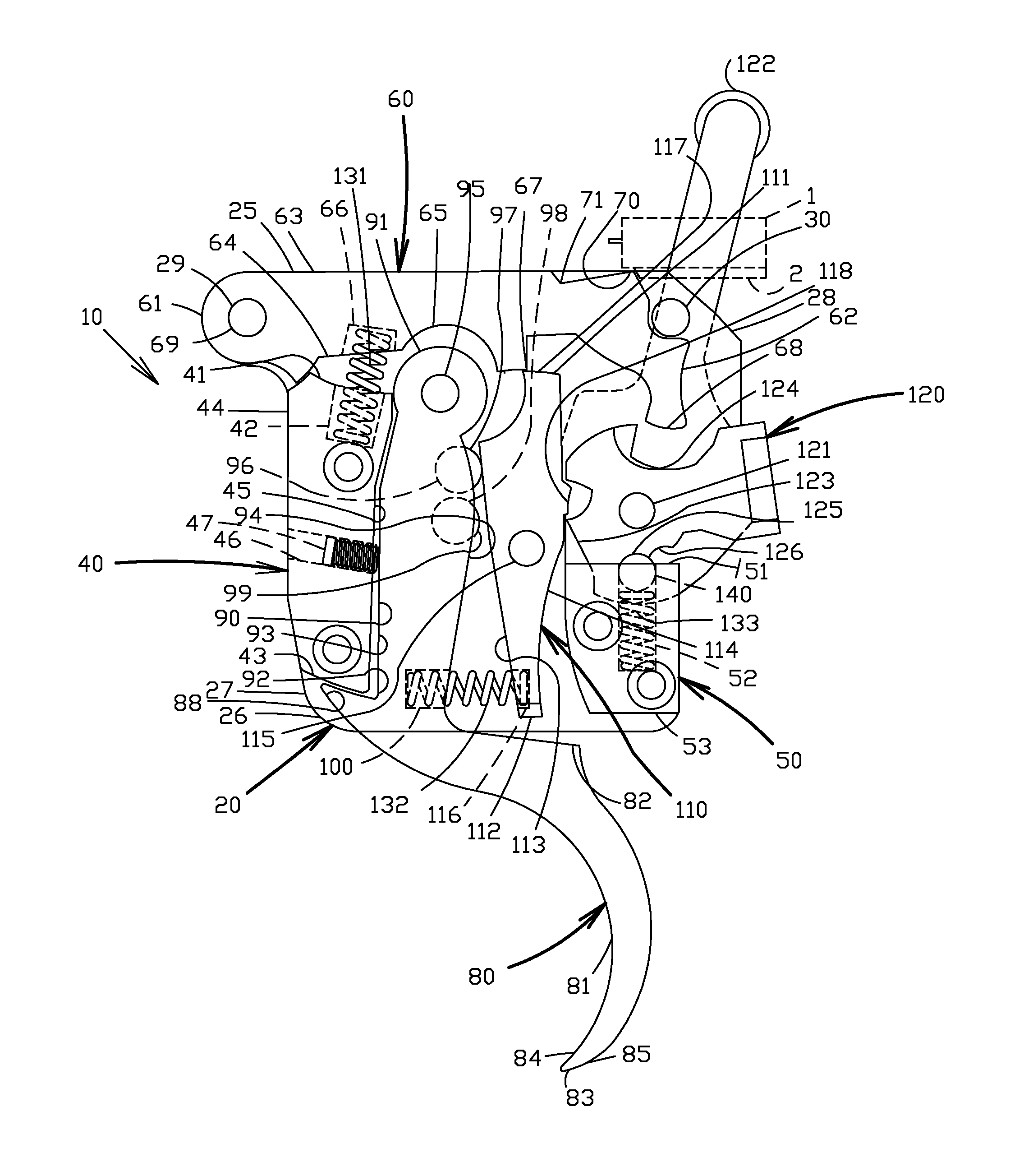
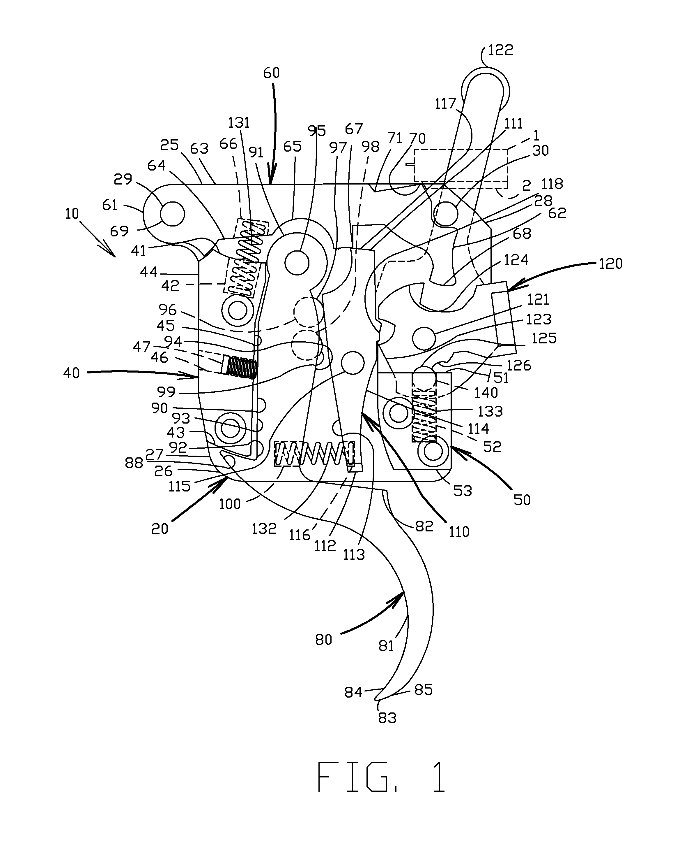
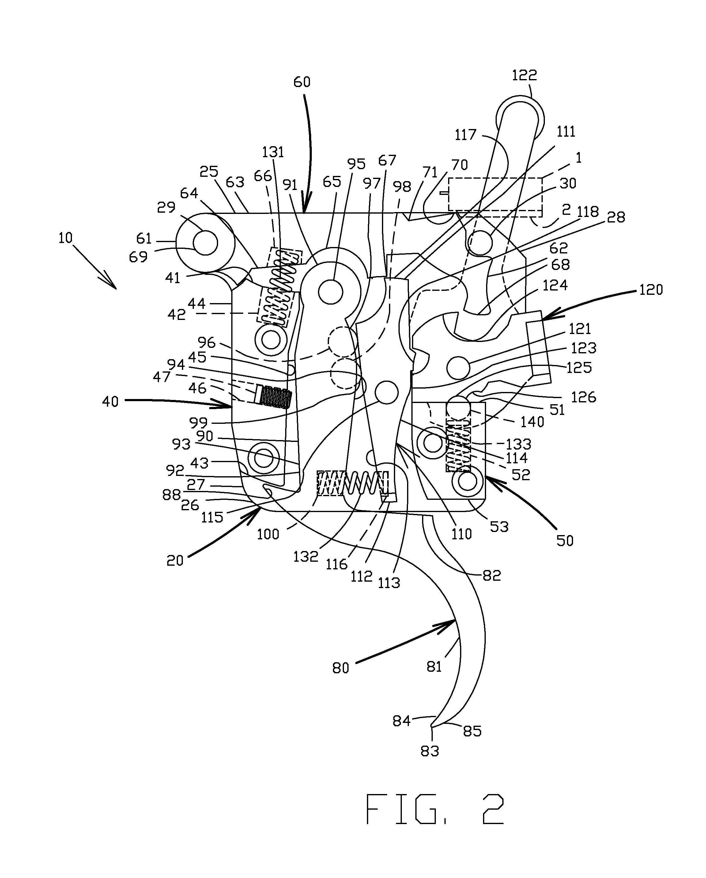
[0037]The present invention can be used with a Remington 700 rifle, and with similar style rifles. In a basic configuration, the firearm has a barrel with a longitudinal axis. The firearm has a cocking piece 1 with a cocking piece contact 2. The cocking piece 1 fires when the cocking piece contact 2 clears the sear (described below).

[0038]Turning now to FIGS. 1-5, a first preferred embodiment of a trigger assembly 10 is provided. The trigger assembly 10 can be a direct replacement for a standard assembly. The trigger assembly 10 has a frame 20, a front spacer block 40, a rear spacer block 50, a sear 60, a trigger 80, ...


PUM


Abstract

A trigger may be pivotally connected to a frame at or near the top of the trigger. A sear transfer bar may be further provided and is pivotally connected to the frame. The pivot in the trigger is higher within the frame as compared to the pivot of the sear transfer bar. Two balls can be between the trigger and the sear transfer bar. The top of the sear transfer bar has a sear contact. Pulling the trigger in a first direction causes the trigger to rotate in a first direction. The sear transfer bar rotates under force of the trigger. The sear transfer bar and the trigger may rotate in opposite directions. The sear will drop when the sear contact of the transfer bar ceases engagement with the sear, causing the firearm to fire. The trigger assembly has a control arm extending beyond the trigger assembly frame.

Description

[0001]This application is a divisional application of pending United States patent application filed on Jan. 31, 2012 and having Ser. No. 13 / 362,201, which itself is a continuation-in-part application of United States patented patent application filed on Oct. 3, 2008 and having application Ser. No. 12 / 245,479 (now U.S. Pat. No. 8,132,349), which itself is a non-provisional application that claims priority on and the benefit of provisional application 60 / 998,009 filed Oct. 5, 2007, the entire contents of each are hereby incorporated herein by reference.BACKGROUND OF THE INVENTION[0002]1. Field of the Invention[0003]The present invention relates to a trigger assembly that can serve as a replacement trigger assembly for a Remington 700 rifle trigger assembly and for other rifles.[0004]2. Description of the Related Art[0005]The Remington 700 rifle is a well regarded firearm. The trigger assembly does generally work well for its intended purposes. Yet, there are some aspects of the trigg...

Claims


Application Information

Patent Timeline
Patent Type & Authority Patents(United States)
IPC IPC(8): F41A17/56F41A19/42F41A19/10
CPCF41A19/10F41A19/42F41A17/56F41A19/12F41A19/16
Inventor HUBER, JOHN, F.
Owner HUBER JOHN F
Learn More