Cylindrical optical ferrule alignment apparatus

a technology of cylindrical optical ferrules and alignment apparatuses, which is applied in the field of adapters, can solve the problems of degrading communication performance in one or more cores, difficult pre-cutting of the internal cavity of the plug housing, and increasing costs, and achieves the effect of low cos

Active Publication Date: 2016-02-09
COMMSCOPE INC
View PDF28 Cites 12 Cited by
  • Summary
  • Abstract
  • Description
  • Claims
  • Application Information

AI Technical Summary

Benefits of technology

[0021]It is an object of the present invention to provide a low cost dependable fiber optic adapter, suitable for multi-core optical fibers.
[0022]It is an object of the present invention to provide an alignment sleeve which is robust and does not require a boss within the adapter housing, which may be snap attached into an adapter housing, and / or which may potentially obviate the need for a two piece adapter housing.
[0023]It is an object of the present invention to provide an alignment sleeve with security keying which may prevent an unauthorized fiber connector from achieving communication mating within an adapter.

Problems solved by technology

It is appreciated that precision molding of the internal cavity of the plug housing is difficult and increases the costs.
Further, the plastic portions of the housing can be subject to abrasion and may over time expand to develop play in the nesting between the external geometry of the ferrule holder and the internal geometry of the plug housing, which could lead to degraded communication performance in one or more cores.

Method used


Image

  • Cylindrical optical ferrule alignment apparatus
  • Cylindrical optical ferrule alignment apparatus
  • Cylindrical optical ferrule alignment apparatus

Examples


first embodiment

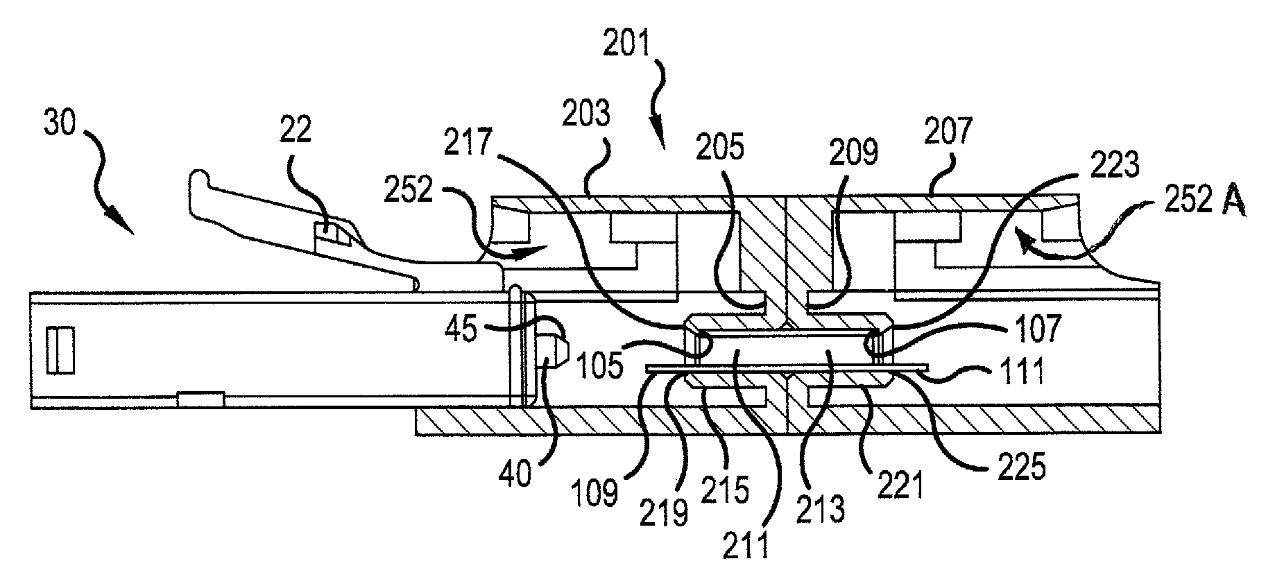
[0055]FIGS. 7-9 show various views of a ferrule alignment sleeve 101, in accordance with the present invention. The sleeve 101 extends in a longitudinal direction 102 and forms an inner, generally tubular area 103. A first rim 105 is formed around a first opening at one end of the tubular area 103 to receive an end of a first circular ferrule 40 (see FIG. 12). A second rim 107 is formed around a second opening at an opposite end of the tubular area 103 to receive an end of a second ferrule 40A.

[0056]A first tab 109 is located adjacent to the first rim 105 and projects away from the tubular area 103. A second tab 111 is located adjacent to the second rim 107 and projects away from the tubular area 103. In a preferred embodiment, the first tab 109 has a generally radiused or triangular tip at its distal end 113, and the second tab 111 also has a generally radiused or triangular tip at its distal end 115.

[0057]In one embodiment, the sleeve 101 is split in a direction parallel to its lo...

second embodiment

[0076]FIGS. 16-18 show various views of a ferrule alignment sleeve 301, in accordance with the present invention. The sleeve 301 extends in a longitudinal direction 302 and forms an inner, generally tubular area 303. A first rim 305 is formed around a first opening at one end of the tubular area 303 to receive an end of a first circular ferrule 40 (see FIG. 21). A second rim 307 is formed around a second opening at an opposite end of the tubular area 303 to receive an end of a second ferrule 40A.

[0077]A first tab 309 is located adjacent to the first rim 305 and projects away from the tubular area 303. A second tab 311 is located adjacent to the second rim 307 and projects away from the tubular area 303. In a preferred embodiment, the first tab 309 has a generally radiused or triangular tip at its distal end 313, and the second tab 311 also has a generally radiused or triangular tip at its distal end 315.

[0078]In one embodiment, the sleeve 301 is split in a direction parallel to its ...


PUM


Abstract

An alignment sleeve for an optical fiber adapter includes features to bring precision alignment between optical fiber cores. The sleeve includes a tubular inner area to accept first and second ferrule ends of first and second connectors. First and second tabs project from first and second ends of the sleeve. The first and second tabs slide into holes in the ferrule holders or barrels of the first and second connectors, so as to provide rotational alignment of the first and second ferrules, which may be presenting multi-core optical fibers. A mid-portion of the sleeve may include geometrical features to enable a snap fit of the sleeve into a housing of the adapter. More than one tab may be employed at the ends of the sleeve, and the tabs may have defined spacing and / or dimensions to enable security keying, only permitting coupling between connectors possessing matching holes in the ferrule barrels.

Description

[0001]This application claims the benefit of U.S. Provisional Application No. 61 / 755,721, filed Jan. 23, 2013, which is herein incorporated by reference.BACKGROUND OF THE INVENTION[0002]1. Field of the Invention[0003]The present invention relates to an adapter for communicating a first fiber optic connector to a second fiber optic connector. More particularly, the present invention relates to an alignment feature of an adapter, which enables precise alignment of the cores of a multi-core fiber end of the first connector with the corresponding cores of a multi-core fiber end of the second connector.[0004]2. Description of the Related Art[0005]FIG. 1 shows an exploded view of a simplex connector, in the form of an LC connector 30, in accordance with the prior art. The LC connector 30 comprises the following components, from left to right: plug housing 31; ferrule subassembly 32; spring 33; extender 34; and buffer boot 35. For the purposes of the present discussion, the adjectives “fro...

Claims


Application Information

Patent Timeline
Patent Type & Authority Patents(United States)
IPC IPC(8): G02B6/38
CPCG02B6/3825G02B6/3877G02B6/3871G02B6/3885
Inventor NIELSON, JEFFREY, D.
Owner COMMSCOPE INC
Why Eureka
Try Eureka