

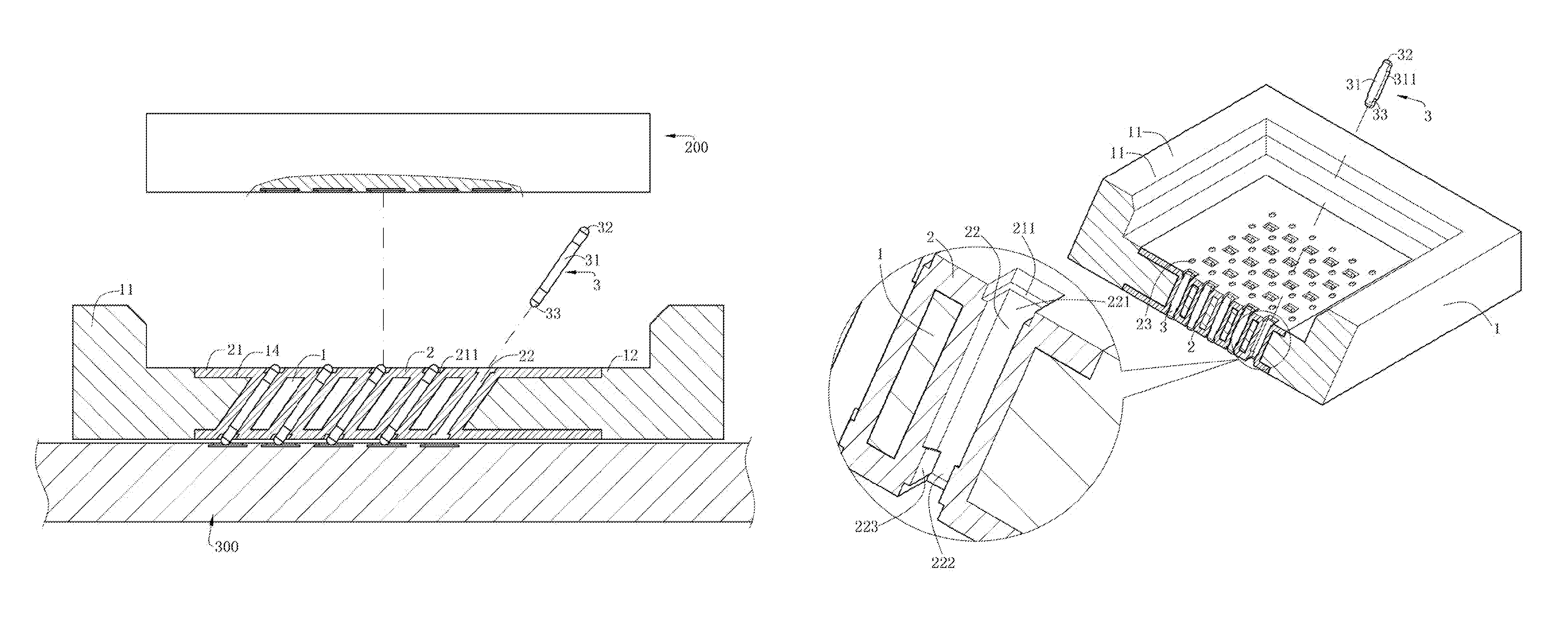
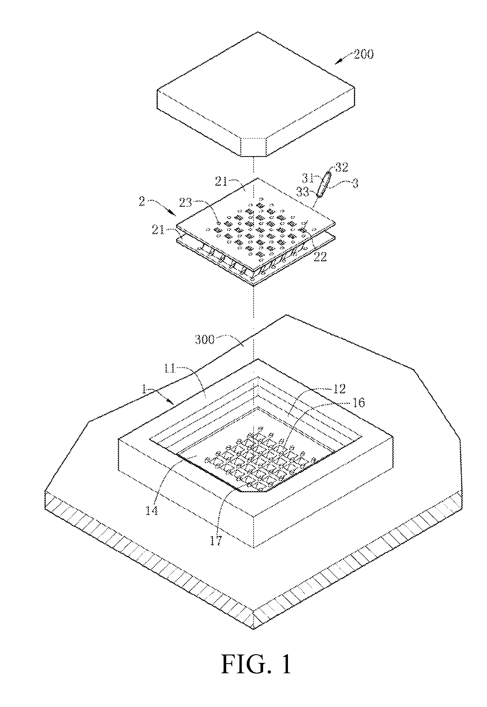
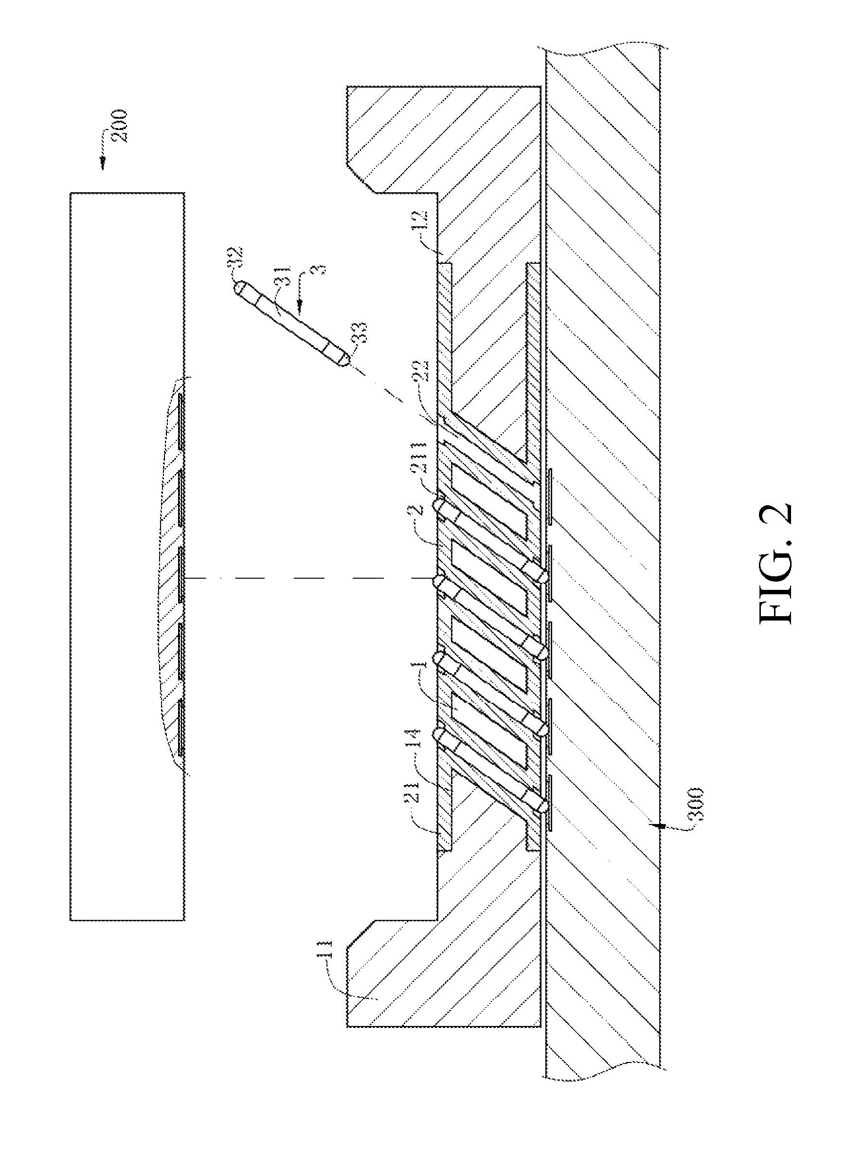
Electrical connector with a plurality of contacts recived in a plurality of slots in a plurality of elastic bodies integrally formed with an insulating body
a technology of elastic bodies and electrical connectors, which is applied in the direction of coupling contact members, coupling device connections, electrical devices, etc., can solve the problems of insufficient normal force (or positive force), affecting the electrical connection between the chip module and the electrical connector, and limited deformation of the contact portion. , to achieve the effect of good mechanical performance and convenient electrical connection
- Summary
- Abstract
- Description
- Claims
- Application Information
AI Technical Summary
Benefits of technology
Problems solved by technology
Method used
Image

Examples
Embodiment Construction
[0043]The present invention is more particularly described in the following examples that are intended as illustrative only since numerous modifications and variations therein will be apparent to those skilled in the art. Various embodiments of the invention are now described in detail. Referring to the drawings, like numbers indicate like components throughout the views. As used in the description herein and throughout the claims that follow, the meaning of “a”, “an”, and “the” includes plural reference unless the context clearly dictates otherwise. Also, as used in the description herein and throughout the claims that follow, the meaning of “in” includes “in” and “on” unless the context clearly dictates otherwise. Moreover, titles or subtitles may be used in the specification for the convenience of a reader, which shall have no influence on the scope of the present invention.
[0044]It will be understood that when an element is referred to as being “on” another element, it can be di...
PUM
 Abstract
Description
Claims
Application Information