Socket having overheating destructive limiting element

a destructive limit element and overheating technology, applied in the direction of overvoltage arrestors using spark gaps, coupling device connections, electrical equipment, etc., can solve the problems of erroneous contact between two terminals, failure of complete disconnection of two terminals, and rise in temperature and become molten and broken, so as to enhance the application safety of circuits

Active Publication Date: 2016-02-09
GREEN IDEA TECH INC
View PDF9 Cites 32 Cited by
  • Summary
  • Abstract
  • Description
  • Claims
  • Application Information

AI Technical Summary

Benefits of technology

[0010]To overcome drawbacks of a power-off structure of a conventional socket and to enhance application safety of circuits, a socket having an overheating destructive limiting element is provided by the present invention.
[0025]1. The limiting element of the present invention is an insulation material. When an operating temperature of the socket gets too high, the limiting element becomes deformed and destructed to change the socket to a turn-off state. Further, the insulating property of the limiting element prevents the destructed limiting element from coming into unintended contact with surrounding electronic elements to ensure safety after disconnecting the power.
[0026]2. In the socket having an overheating destructive limiting element of the present invention, without involving rivet openings as used in a convention solution, the live wire terminal, the live wire conductive plate, and / or the neutral wire terminal and the neutral wire conductive plate are secured at a turn-on position. Not only a processing procedure is simplified, but also sufficient contact areas are provided between the live wire terminal, the live wire conductive plate, and / or the neutral wire terminal and the neutral wire conductive plate to mitigate the rise in temperature when the current passes through.
[0027]3. In the socket having an overheating destructive limiting element of the present invention, respective fastening portions for fastening with one another are provided at the live wire terminal, the live wire conductive plate, and / or the neutral wire terminal and the neutral wire conductive plate. Further, the first positioning portion and the second positioning portion that position with each other are provided at the limiting element. As such, it is ensured that the live wire terminal, the live wire conductive plate, the neutral wire terminal and the neutral wire conductive plate are positioned and prevented from dislocation. Therefore, during an installation process, the live wire terminal and the neutral wire terminal are allowed to precisely align with the live wire hole and the neutral wire hole at the housing to effectively maintain a product yield rate.
[0029]5. For an extension socket, multiple sets of live wire terminals “individually” come into contact with a live wire conductive plate, and multiple sets of neutral wire terminals also “individually” come into contact with a neutral wire conductive plate. When any set of the live wire terminals disengages from the live wire conductive plate to become open circuit or any set of the neutral wire terminals disengages from the neutral wire conductive plate to become open circuit, a power-on state of other live wire terminals with the live wire conductive plate and a power-on state of other neutral wire terminals with the neutral wire conductive plate are kept unaffected. That is, for an extension socket, when any of multiple sets of socket units becomes turned off due to overheating, other non-overheated socket units are maintained powered on and are capable of continuing supplying power. More particularly, as the limiting element has a small volume, an extension socket allows every socket to be individually powered off by requiring almost no additional volume.

Problems solved by technology

In the event of current overload, circuit overheating or an excessively high ambient temperature, the meltable metal is heated to cause a rise in the temperature and becomes molten and broken.
As a result, the two terminals intended to be disconnected may again erroneously come in contact to form close circuit.
If a part of the molten meltable metal remains stuck to the two terminals, the stuck molten meltable metal may also result in an erroneous contact between the two terminals to fail in a complete disconnection.
Further, the expelled molten meltable metal also has a chance of coming into contact with other surrounding electronic elements to cause a short circuit.
Therefore, such conventional solution is exposed to potential hazards and needs to be improved.
Thirdly, a conventional overload protector has a large volume.
Whether for storage, transportation or usage, such excessive volume inevitably causes complications and inconveniences.

Method used


Image

  • Socket having overheating destructive limiting element
  • Socket having overheating destructive limiting element
  • Socket having overheating destructive limiting element

Examples


first embodiment

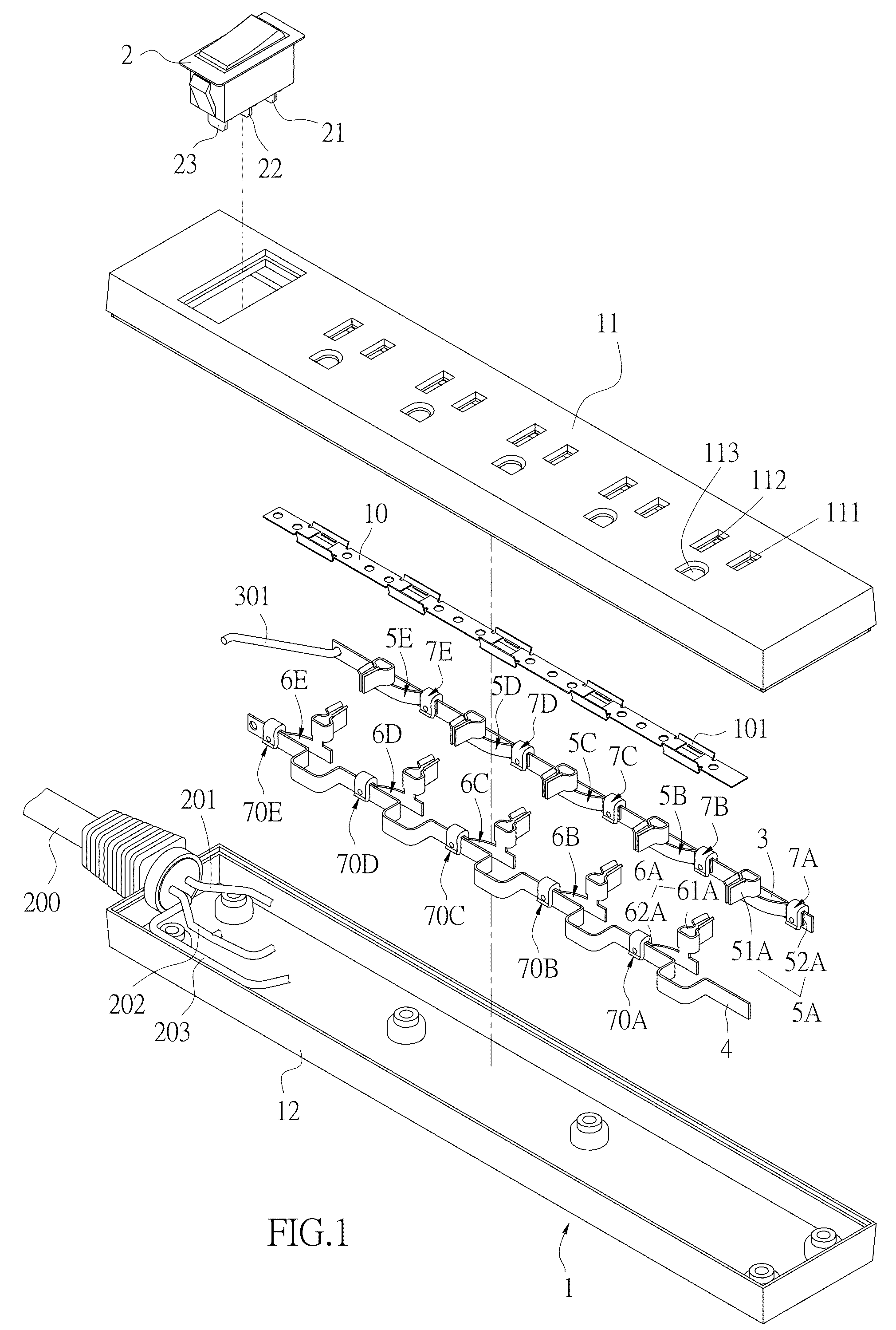
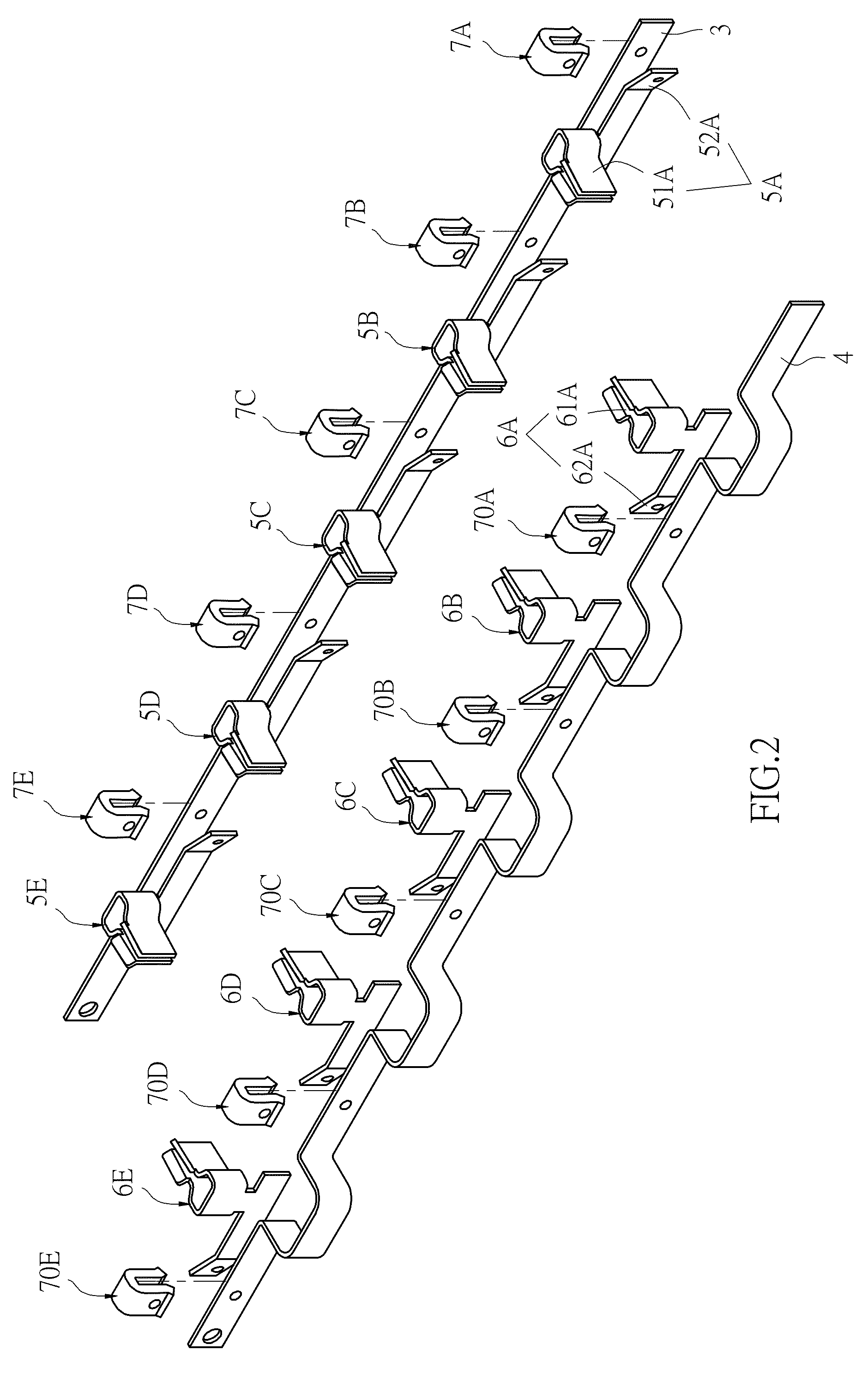
[0052]Referring to FIG. 1 and FIG. 2, a socket having an overheating destructive limiting element according to the present invention includes a housing 1, a switch 2, a live wire conductive plate 3, a neutral wire conductive plate 4, a plurality of live wire terminals 5A, 5B, 5C, 5D and 5E, a plurality of neutral wire terminals 6A,6B, 6C, 6D and 6E, and a plurality of limiting elements 7A, 7B, 7C, 7D, 7E, 70A, 70B, 70C, 70D and 70E.

[0053]The housing 1 includes an upper casing 11 and a lower casing 12 that may be assembled to each other. The upper casing 11 includes a plurality of live wire holes 111 and a plurality of neutral wire holes 112.

[0054]The switch 2 includes a live wire input end 21, a live wire output end 22, and a neutral wire end 23. The live wire input end 21 is for connecting to a live wire conductive wire 201 of a power line 200. The neutral wire end 23 is for connecting to a neutral wire conductive wire 202 of the power line 200.

[0055]The live wire conductive plate ...

sixth embodiment

[0074]FIG. 15A and FIG. 15B show the present invention. In the sixth embodiment, a limiting element 700D is formed by a pair of cover bodies 70 and 700 correspondingly combined to each other. For example, means for combining the cover bodies 70 and 700 may be ultrasonic welding, embedding or adhesion. The cover bodies 70 and 700 define chambers 701A and 701B, respectively, which are in communication with openings 702A and 702B of the chambers 701A and 702B, respectively. An inner side of the cover body 70 opposite the opening 702A is provided with a first insulation portion 71C, and an inner side of the other cover body 700 is correspondingly provided with the second insulation portion 72C, so as to clamp the live wire conductive plate 3A and the live wire contact portion 520A.

seventh embodiment

[0075]Referring to FIG. 16 also showing the present invention, the limiting element 700D is a ring body, and the first insulation portion 71D and the second insulation portion 72D of the limiting element 700D are both located at the inner side of the ring body. As such, the live wire conductive plate 3A and the live wire contact portion 520A are also similarly clamped to form the turn-on position.


PUM


Abstract

A socket having an overheating destructive limiting element includes a housing, a live wire conductive plate, a neutral wire conductive plate, at least one live wire terminal, at least one neutral wire terminal, and at least one limiting element. The live wire terminal includes a live wire contact portion in contact with the live wire conductive plate. The neutral wire terminal includes a neutral wire contact portion in contact with the neutral wire conductive plate. The limiting element is an insulating body, and is placed at contact parts of the live wire conductive plate and the live wire contact portion, and / or at contact parts of the neutral wire conductive plate and the neutral wire contact portion. When an operating temperature becomes excessively high, the limiting element becomes deformed and destructed to form a turn-off position.

Description

BACKGROUND OF THE INVENTION[0001]a) Field of the Invention[0002]The invention relates in general to a socket having an overheating destructive limiting element, and more particularly, to a socket having a limiting element made of an insulation material that positions a live wire terminal, a live wire conductive plate and / or a neutral wire terminal and a neutral conductive plate at a turn-on position. When an operating temperature gets too high, the limiting element becomes deformed and destructed to change the live wire terminal, the live wire conductive plate and / or the neutral wire terminal and the neutral conductive plate to a turn-off position.[0003]b) Description of the Prior Art[0004]To prevent a circuit from issues of current overload, short circuit and overheating, a fuse or an overload protector is usually provided at the circuit. When the temperature of the circuit gets too high or the current gets too large, the fuse affected by the high temperature becomes blown or a bi-...

Claims


Application Information

Patent Timeline
Patent Type & Authority Patents(United States)
IPC IPC(8): H01T1/14H01T4/06H01R13/68
CPCH01R13/68
Inventor WANG, CHUAN-SHENG
Owner GREEN IDEA TECH INC
Why Eureka
Try Eureka