
Wiper arm assembly having pivotal cover allowing access to pivot shaft

a technology of pivot shaft and wiper arm, which is applied in the direction of vehicle maintenance, vehicle cleaning, transportation and packaging, etc., can solve the problems of more assembly effort of the wiper arm, unintentional latching of many wiper arms, and difficult final assembly, so as to eliminate the problem, facilitate the dislodge or inadvertent removal, and efficiently and effectively provide access

Active Publication Date: 2016-02-16
TRICO PROD CORP
View PDF46 Cites 1 Cited by
  • Summary
  • Abstract
  • Description
  • Claims
  • Application Information

AI Technical Summary

Benefits of technology

The solution reduces assembly effort, prevents unintentional latching, and minimizes cover dislodgment during washing, enhancing the efficiency and reliability of the wiper arm assembly.

Problems solved by technology

While such wiper systems known in the related art have generally worked for their intended purposes, some deficiencies still remain.
Many covers of these type are susceptible to unintentional latching prior to assembly and may require an extra component for final assembly.
Moreover, the covers do not stay up prior to assembly, making final assembly difficult.
Farther, the covers may result in more assembly effort of the wiper arm.
Moreover, covers of these type are also susceptible to snagging on brushes or cloths, typically employed in car washes, and can be inadvertently removed from the arm and thus lost during this process.
These problems are not limited to, but are especially prevalent in connection with wiper systems used to clean a rear window of the vehicle.
Thus, there remains a need in the art for a wiper arm assembly that employs a cover that efficiently and effectively provides for access to the pivot shaft, but which is not susceptible to unintentional latching prior to assembly and which is not easily dislodged or inadvertently removed during the process of washing the car and other interference with the wiper arm assembly.

Method used


Image

  • Wiper arm assembly having pivotal cover allowing access to pivot shaft
  • Wiper arm assembly having pivotal cover allowing access to pivot shaft
  • Wiper arm assembly having pivotal cover allowing access to pivot shaft

Examples


Embodiment Construction

)

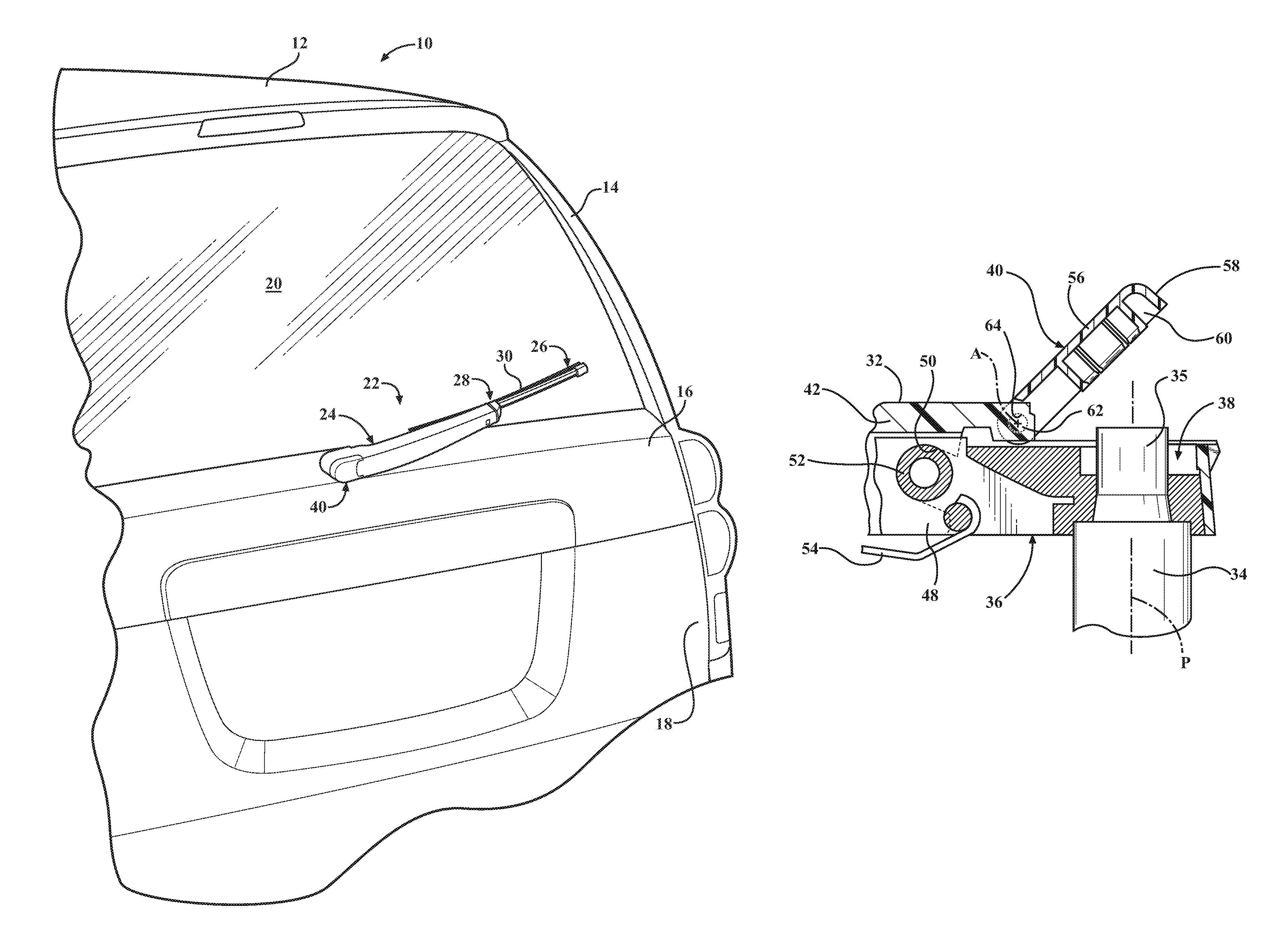
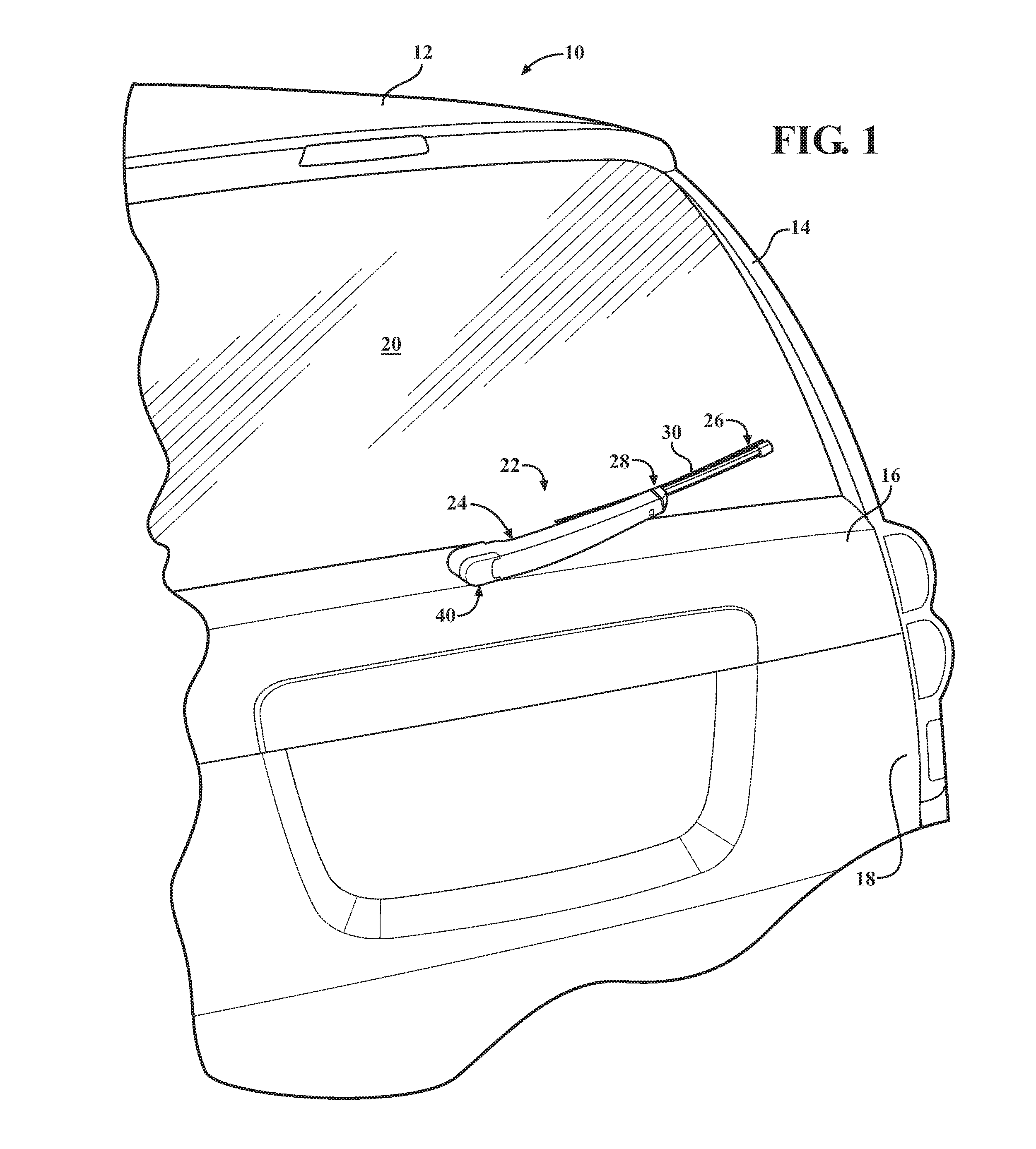
[0018]Referring now to the figures, where like numerals are used to designate like structure, a portion of a vehicle is schematically illustrated at 10 in FIG. 1. More specifically, the portion of the vehicle that has been employed to illustrate the present invention includes a generic illustration of a rear of a vehicle. Thus, the vehicle 10 includes a roof 12, a pair of pillars 14 (only one of which is shown in FIG. 1), a lift gate 16, and a rear 18 of the vehicle 10. A glass rear window 20 extends between the pillars 14 on the lift gate 16. While the rear of the vehicle 10 illustrated herein employs a lift gate 16, those having ordinary skill in the art will appreciate from the description that follows that the vehicle 10 could include a hatch back or any other commonly known configuration without departing from the scope of the present invention.

[0019]A wiper system is generally shown at 22 in FIG. 1 and in the embodiment illustrated herein, is employed to clean the rear window...


PUM


Abstract

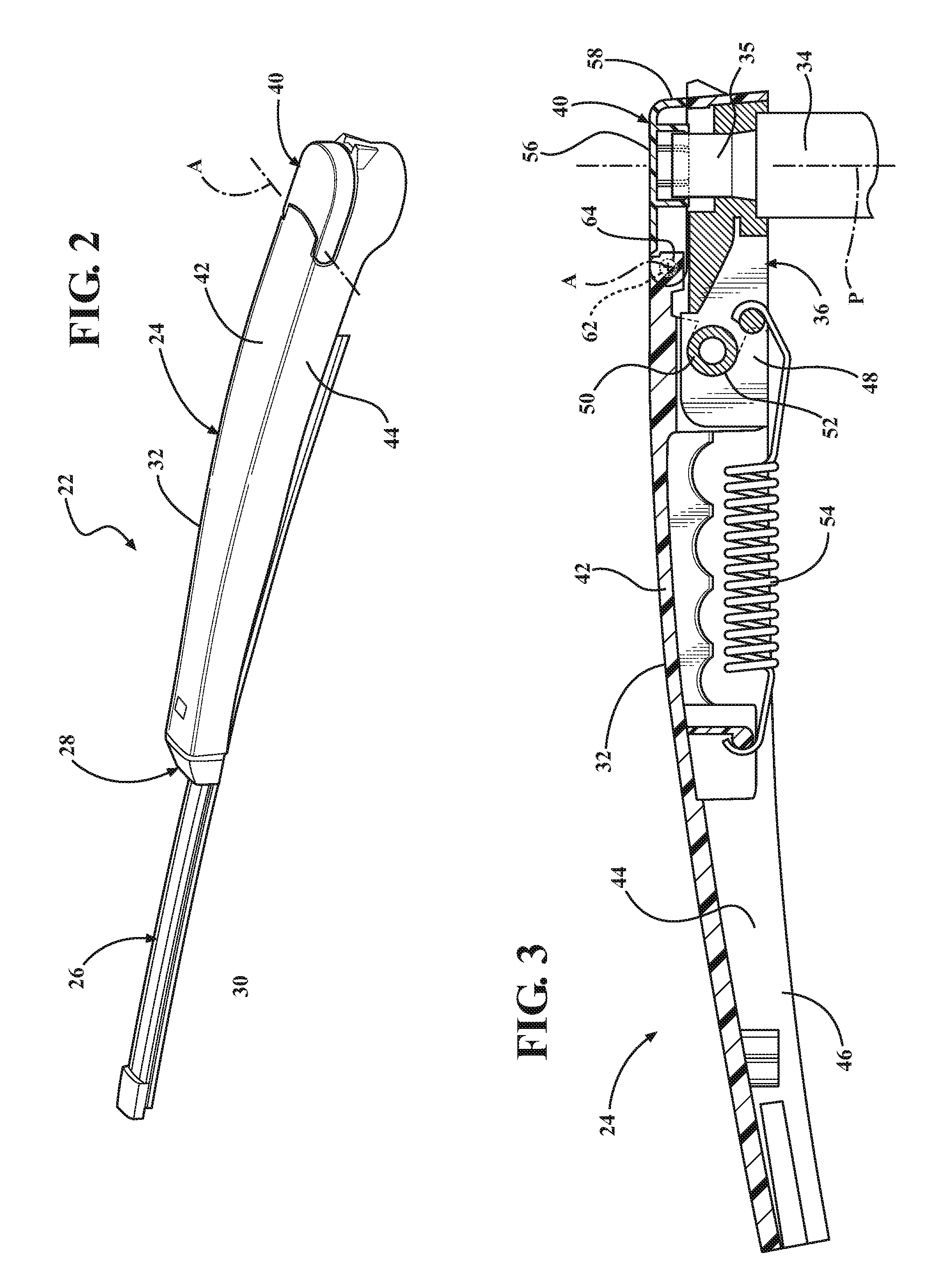
A wiper arm assembly is adapted to support a wiper blade as it moves across a surface to be wiped. The wiper arm assembly includes a body and a head supported by the body and adapted to be mounted to a pivot shaft that defines a pivot axis P and drives the wiper blade in an oscillating manner across the surface to be wiped. The body also includes an opening providing access to the head mounted to the pivot shaft. The wiper arm assembly includes a cover pivotally mounted to the body at the opening and is movable about an axis A substantially perpendicular to the pivot axis P from a first position closing the opening to a second position allowing access to the head. A locking mechanism on the cover locks the cover to a nut on the pivot shaft to retain the cover in the first position closing the opening.

Description

BACKGROUND OF THE INVENTION[0001]1. Field of the Invention[0002]The present invention relates generally to wiper systems for vehicles and, more specifically, to a wiper arm assembly for a wiper system of a vehicle that is adapted to support a wiper assembly as it moves across a surface to be wiped and having a pivotal cover that allows access to a pivot shaft.[0003]2. Description of the Related Art[0004]Conventional wiper systems known in the related art include some type of wiper assembly mounted to a wiper arm assembly, which, in turn, is mounted adjacent to a surface to be wiped, such as a windshield. The wiper arm assembly is pivotally driven to impart reciprocal motion to the wiper assembly across the windshield. The wiper assembly includes a wiping element that contacts the windshield across the surface to be wiped. The wiper assembly is commonly either of the “tournament” or “beam blade” type. Both types of wiper assemblies commonly known in the related art typically incorpor...

Claims


Application Information

Patent Timeline
Patent Type & Authority Patents(United States)
IPC IPC(8): B60S1/34
CPCB60S1/3484B60S1/345B60S1/3481
Inventor MOLL, KYLE
Owner TRICO PROD CORP
Learn More