Image forming apparatus

a technology of image forming apparatus and forming apparatus, which is applied in the direction of electrographic process apparatus, instruments, optics, etc., can solve the problems of inability to appropriately control the laser emission timing of light emitting elements, measurement errors will occur, and change in measurement, so as to improve correction accuracy and suppress measurement errors

Active Publication Date: 2016-02-16
CANON KK
View PDF6 Cites 13 Cited by
  • Summary
  • Abstract
  • Description
  • Claims
  • Application Information

AI Technical Summary

Benefits of technology

[0013]The present invention has been made in view of the above-mentioned problems. The present invention in one aspect provides a technique of, in an image forming apparatus including multiple light emitting elements, suppressing measurement errors when measuring an interval between light beams emitted from two light emitting elements, and improving correction accuracy for the image writing start positions of the light emitting elements.
[0015]According to the present invention, it is possible to provide a technique of, in an image forming apparatus including multiple light emitting elements, suppressing measurement errors when measuring an interval between light beams emitted from two light emitting elements, and improving correction accuracy for the image writing start positions of the light emitting elements.

Problems solved by technology

However, the following problems are present in the method for measuring the detection time interval of light beams (i.e., beam interval) by the BD sensor as described above.
For this reason, there is a possibility that a measurement error will occur due to a change in the measurement result of the time interval (beam interval) between pulses (BD signals) generated by the BD sensor changing when the incident light power on the BD sensor changes.
As shown in FIG. 8, when the light power of a light beam that is incident on the BD sensor changes, an error occurs in the measurement result of the time interval between the pulses generated by the BD sensor, and as a result, it is no longer possible to appropriately control the laser emission timings of the light emitting elements.

Method used


Image

  • Image forming apparatus
  • Image forming apparatus
  • Image forming apparatus

Examples


first embodiment

[0034]Hardware Configuration of Image Forming Apparatus

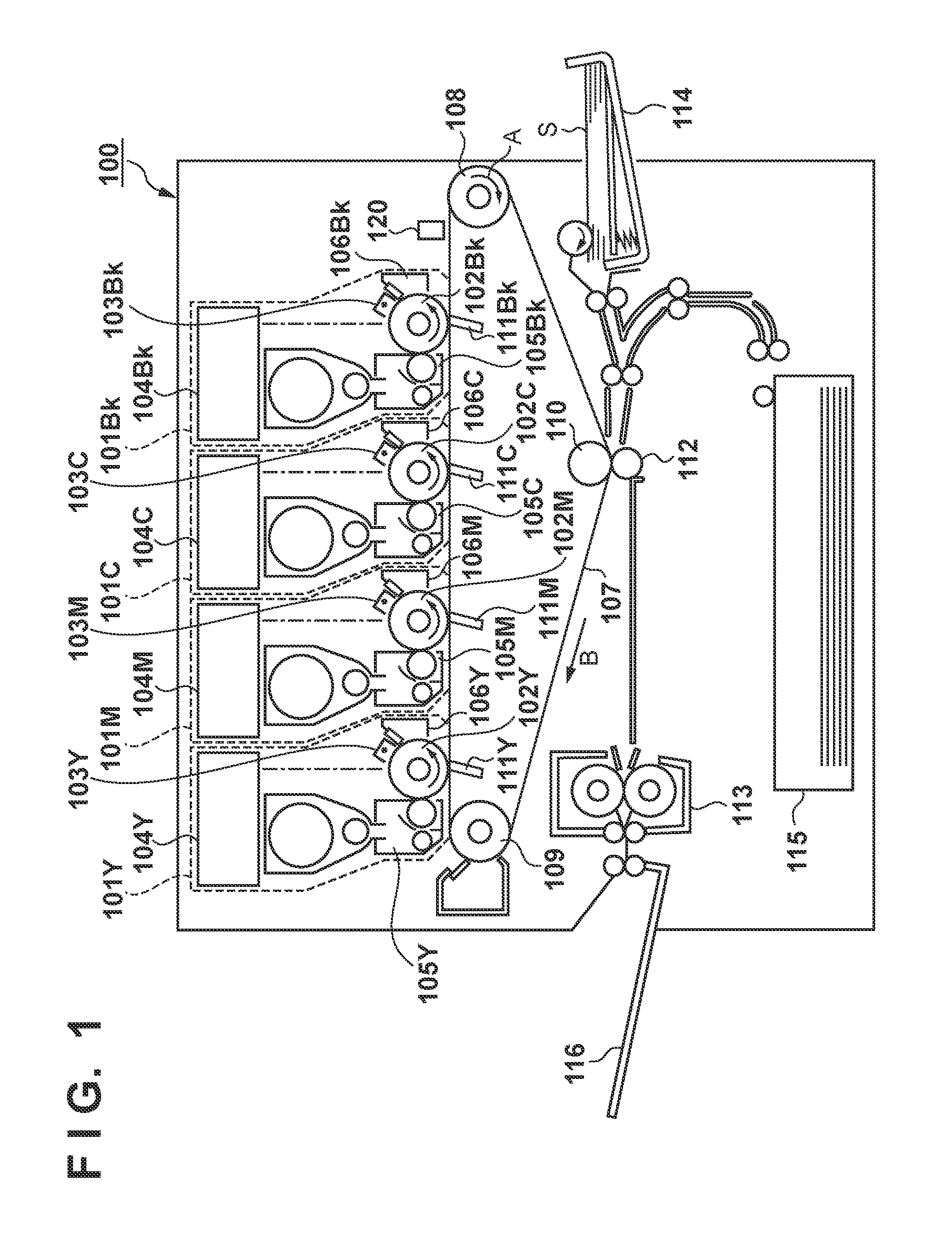
[0035]First, a configuration of an image forming apparatus 100 according to the present embodiment will be described with reference to FIG. 1. The image forming apparatus 100 includes four image forming units 101Y, 101M, 101C, and 101Bk that form images (toner images) using yellow (Y), magenta (M), cyan (C), and black (Bk) toner respectively.

[0036]The image forming units 101Y, 101M, 101C, and 101Bk include photosensitive drums (photosensitive members) 102Y, 102M, 102C, and 102Bk respectively. Charging units 103Y, 103M, 103C, and 103Bk, optical scanning apparatuses 104Y, 104M, 104C, and 104Bk, and developing units 105Y, 105M, 105C, and 105Bk are arranged in the vicinity of the photosensitive drums 102Y, 102M, 102C, and 102Bk respectively. Drum cleaning units 106Y, 106M, 106C, and 106Bk are furthermore arranged in the vicinity of the photosensitive drums 102Y, 102M, 102C, and 102Bk respectively.

[0037]An intermediate transfer belt ...

second embodiment

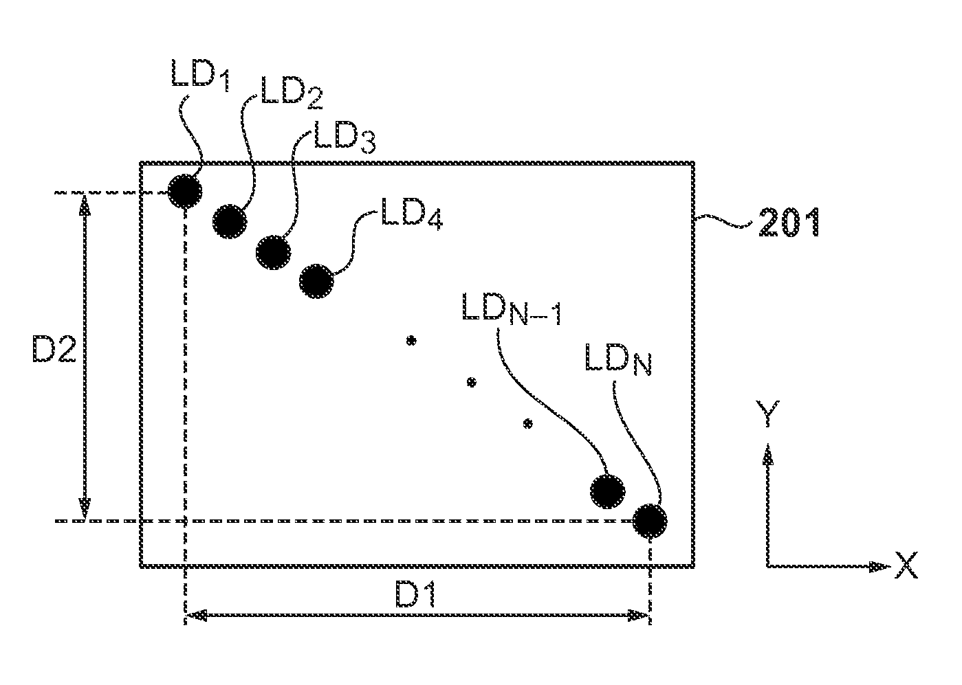
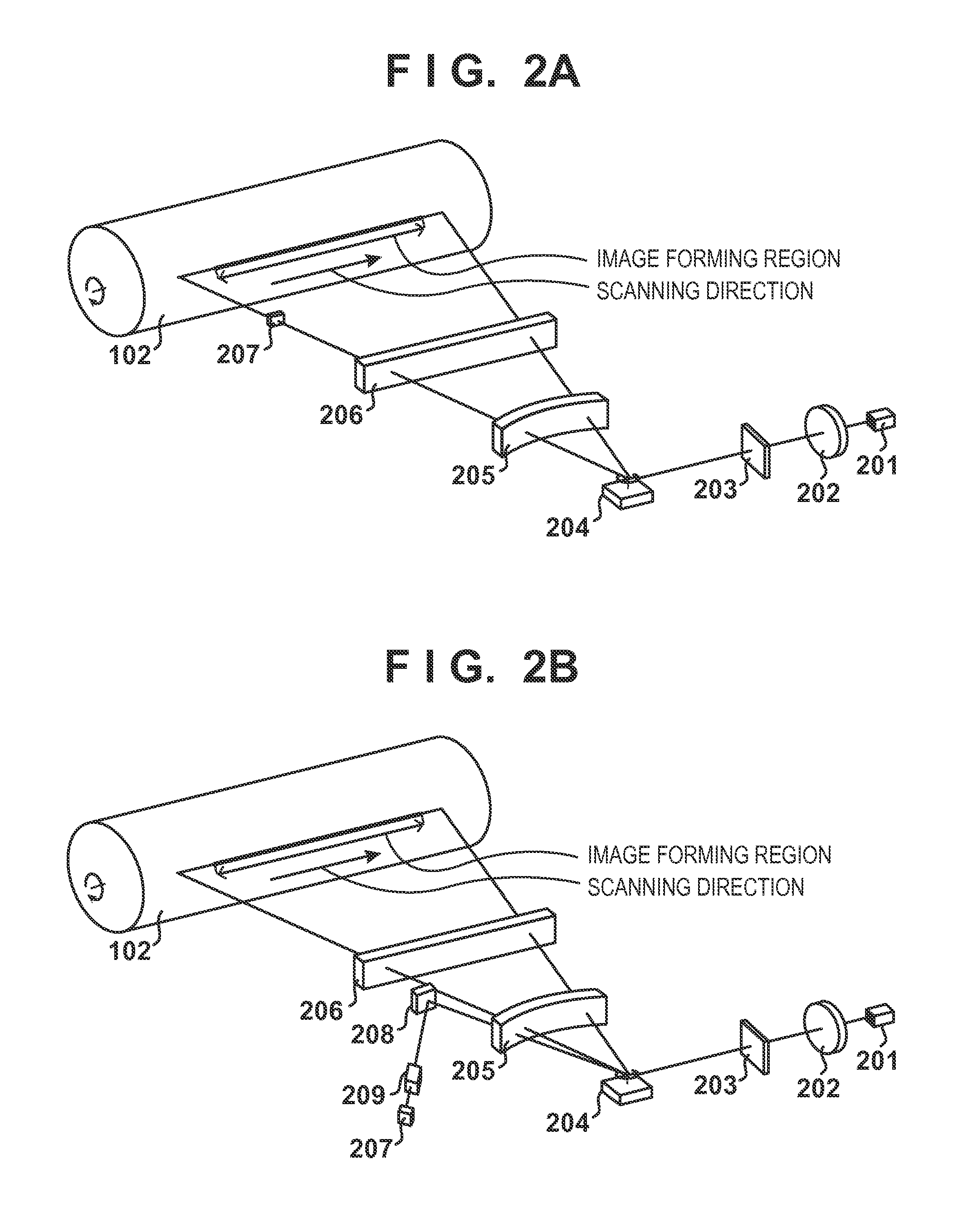
[0125]In the above-described first embodiment, the light emitting elements 1 and N that are to be used in the measurement are subjected to APC before the beam interval measurement is started, such that the light powers correspond to the light power target value set using the above-described density adjustment operation. In this case, for example, when a relatively low value is set as the light power target value, the incident light power on the BD sensor 207 decreases, and there is a possibility that the rising rate of the waveform of the BD signal output from the BD sensor 207 will decrease. As a result, there is a possibility that an irregularity such as a jitter will appear in the measurement result for the BD signal time interval.

[0126]In view of this, as a second embodiment, an example will be described in which, in order to furthermore improve the measurement accuracy for the time interval (beam interval) between the BD signals, the light power target value is set such that th...


PUM


Abstract

An image forming apparatus according to one aspect controls a light source such that first and second laser beams emitted from first and second light emitting elements respectively are incident on a BD sensor successively, and measures the time interval between two BD signals, output from the BD sensor, that correspond to the first and second laser beams. When performing the measurement, the image forming apparatus controls the light powers of the first and second light beams so as to be light powers determined in advance using APC. According to this, measurement errors when measuring the interval between the light beams emitted from the two light emitting elements are suppressed, and correction accuracy for the image writing start positions for the multiple light emitting elements is improved.

Description

BACKGROUND OF THE INVENTION[0001]1. Field of the Invention[0002]The present invention relates to an electrophotographic image forming apparatus.[0003]2. Description of the Related Art[0004]Image forming apparatuses are known which form electrostatic latent images on a photosensitive member by deflecting a light beam emitted from a light source using a rotating polygonal mirror and scanning the photosensitive member using the deflected light beam. This kind of image forming apparatus includes an optical sensor for detecting the light beam deflected by the rotating polygonal mirror (beam detection (BD) sensor), and the optical sensor generates a synchronization signal upon detecting the light beam. By causing the light beam to be emitted from the light source at a timing that is determined using the synchronization signal generated by the optical sensor as a reference, the image forming apparatus keeps constant the writing start position for the electrostatic latent image (image) in t...

Claims


Application Information

Patent Timeline
Patent Type & Authority Patents(United States)
IPC IPC(8): G03G15/04G03G15/043
CPCG03G15/04072G03G15/0435G03G2215/0129G03G15/043
Inventor FURUTA, YASUTOMO
Owner CANON KK
Why Eureka
Try Eureka