Paper feed apparatus, image reading apparatus comprising paper feed apparatus, and image forming apparatus comprising image reading apparatus

a paper feed and paper feed technology, applied in the direction of registering devices, thin material processing, article separation, etc., can solve the problem of insufficient feeding of second width paper, and achieve the effect of simplifying the shape of the second regulating portion and canceling the paper movemen

Active Publication Date: 2016-02-23
SHARP KK
View PDF3 Cites 3 Cited by
  • Summary
  • Abstract
  • Description
  • Claims
  • Application Information

AI Technical Summary

Benefits of technology

[0008]It is another object of the present invention to provide a paper feed apparatus, an image reading apparatus comprising a paper feed apparatus and an image forming apparatus comprising an image reading apparatus, capable of adequately feeding a second width paper such as a name card in addition to a first width paper such as A4 paper that is normally used.
[0036]According to the tenth invention, an operation and an advantage similar to those of the tenth invention can be expected, and it is possible to adequately feed the second width paper such as a name card in addition to the first width paper such as A4 paper.

Problems solved by technology

Therefore, it is impossible to adequately feed the second width paper.

Method used


Image

  • Paper feed apparatus, image reading apparatus comprising paper feed apparatus, and image forming apparatus comprising image reading apparatus
  • Paper feed apparatus, image reading apparatus comprising paper feed apparatus, and image forming apparatus comprising image reading apparatus
  • Paper feed apparatus, image reading apparatus comprising paper feed apparatus, and image forming apparatus comprising image reading apparatus

Examples


first embodiment

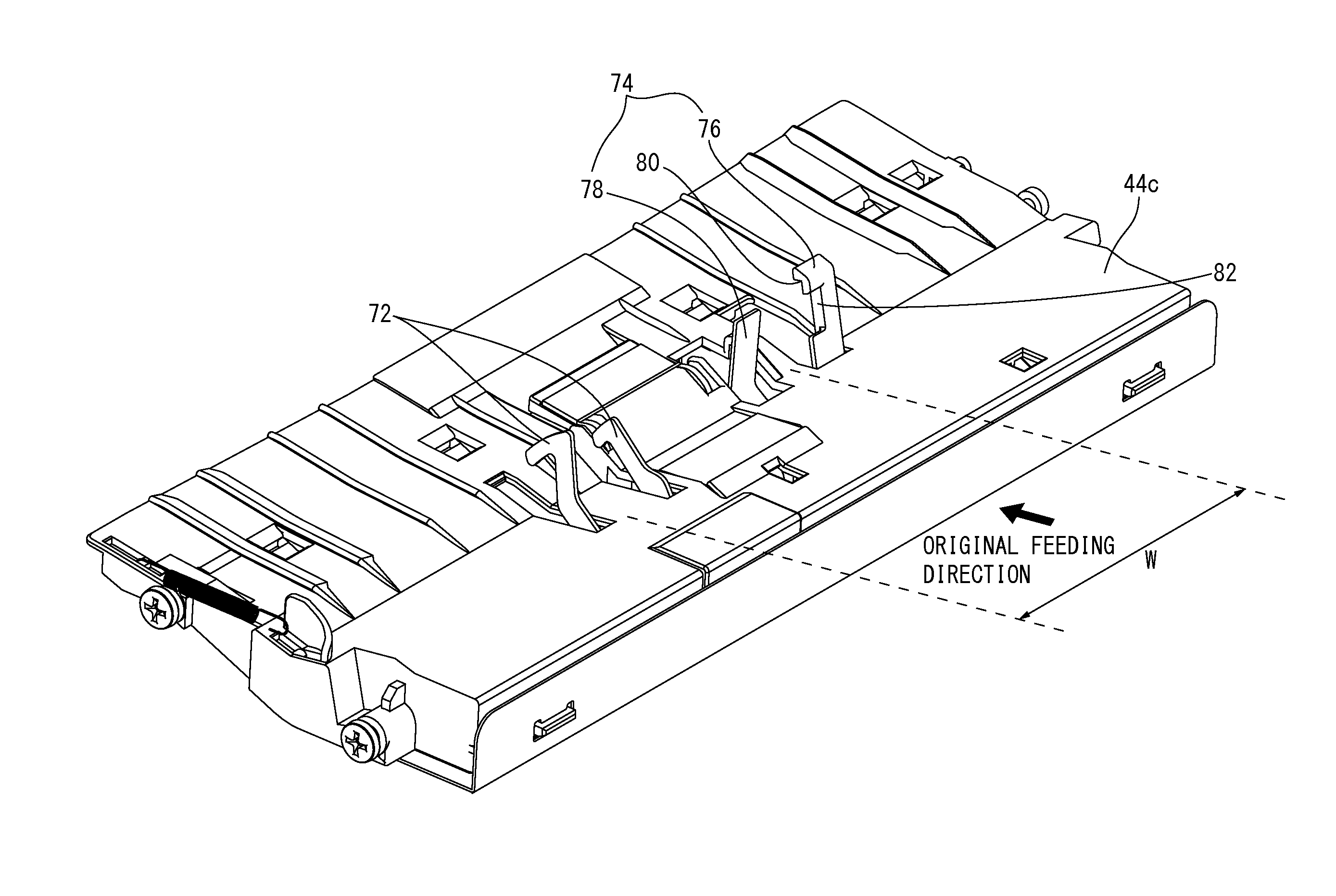
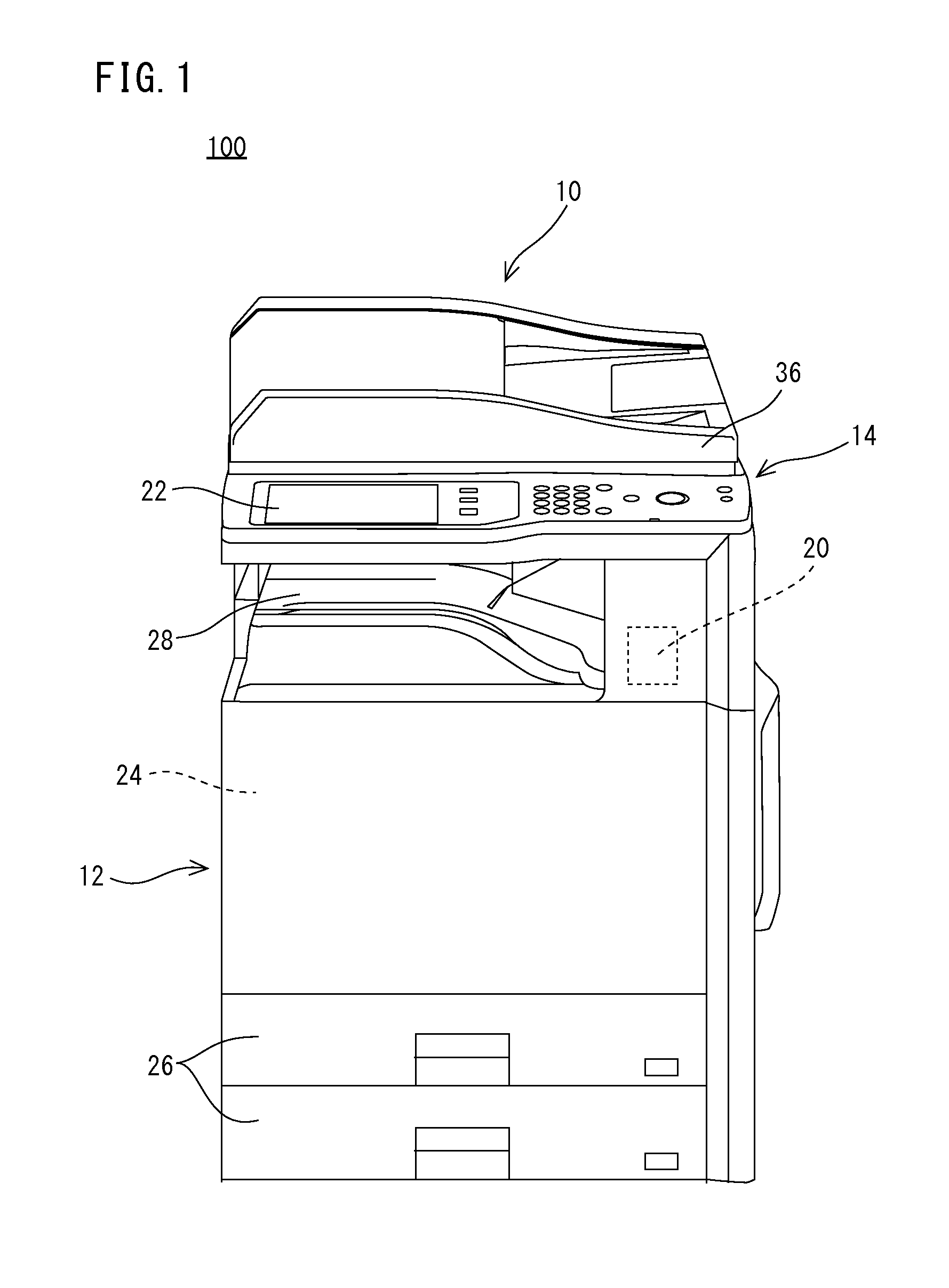
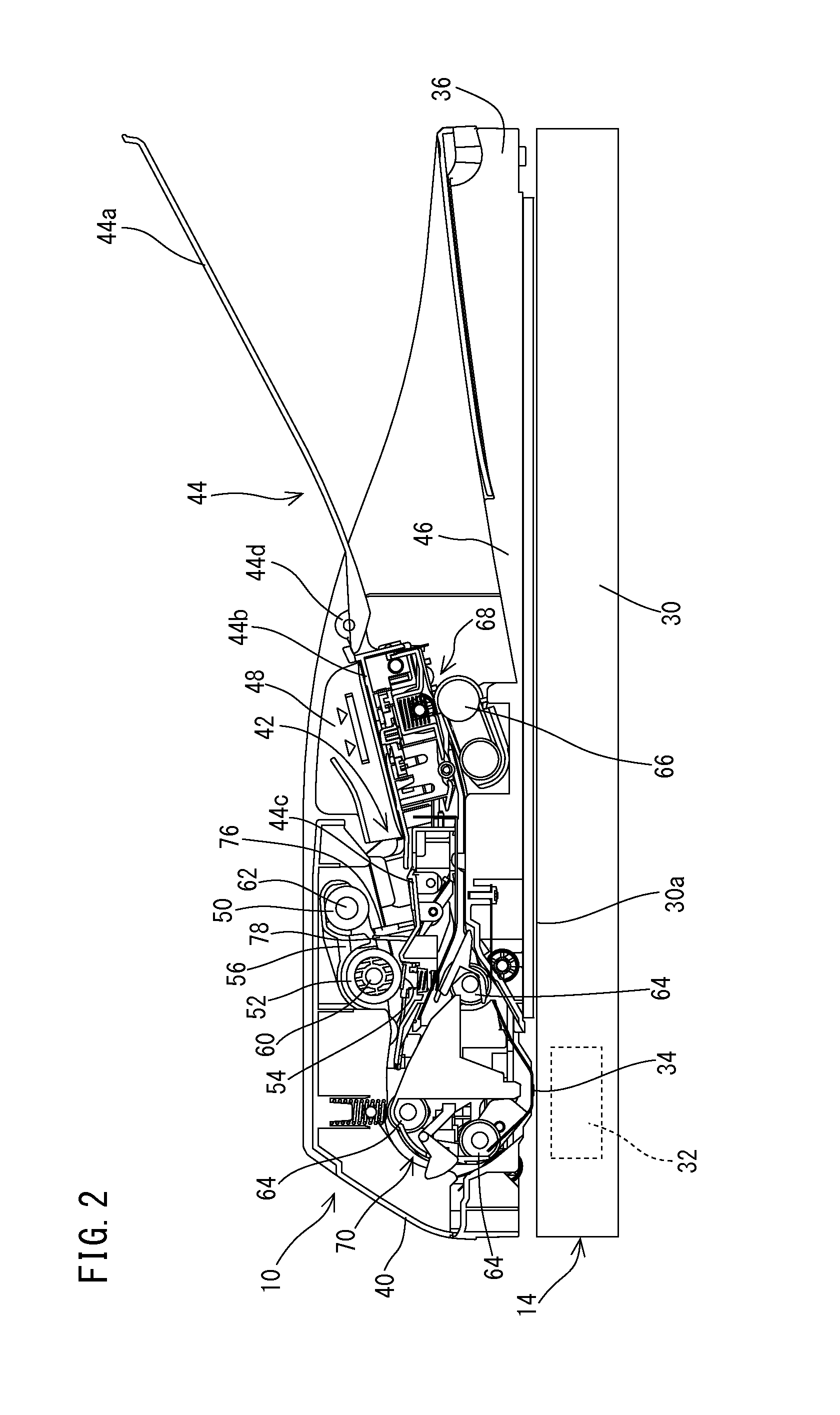
[0051]With referring to FIG. 1 and FIG. 2, a paper feed apparatus 10 of one embodiment according to the present invention is used in an image forming apparatus such as a copying machine, a facsimile, a printer, a multifunction machine compounding these, etc. As details will be described later, the paper feed apparatus 10 comprises a paper placing tray 44, a pickup roller 50, a paper feeding roller 52, a first regulating portion 76, a second regulating portion 78, etc., and automatically feeds a paper (an original) placed in the paper placing tray 44 to an image reading position 34 one by one. In this first embodiment, an example that the paper feed apparatus 10 is applied to a multifunction machine 100 having a copying machine function, a printer function, a scanner function, a facsimile function, etc. is shown.

[0052]First, structure of the multifunction machine 100 is roughly described. As shown in FIG. 1 and FIG. 2, the multifunction machine 100 includes a machine body 12, an imag...

second embodiment

[0079]Next, with referring to FIG. 10 to FIG. 13, a paper feed apparatus 10 that is a second embodiment according to the present invention will be described. Although the regulating member 74 (the first regulating portion 76 and the second regulating portion 78) is rotated in the original feeding direction in sending-out the original in the above-described first embodiment, this second embodiment is different from the first embodiment in a point that the regulating member 74 is rotated in the direction orthogonally intersecting the original feeding direction. In the following, the paper feed apparatus 10 according to the second embodiment will be described with referring to FIG. 10 to FIG. 13, but by applying the same reference numerals for components common to the above-described first embodiment, a duplicate description will be omitted or simplified. Then, only the regulating member 74 and periphery components thereof will be described.

[0080]As shown in FIG. 10 and FIG. 11, a regu...

third embodiment

[0094]Subsequently, a paper feed apparatus 10 that is the third embodiment according to the present invention will be described. The third embodiment is different from the first and second embodiments in a point that although the first regulating portion 76 and the second regulating portion 78 are arranged only at one side of the pickup roller 50 in the above-described first and second embodiments, in the third embodiment, each of the first regulating portion 76 and the second regulating portion 78 is arranged at each of both sides of the pickup roller 50. That is, in the third embodiment, although not shown, at respective sides of the pickup roller 50, the first regulating portion 76 is provided outside the second width paper passage area W in the direction orthogonally intersecting the original feeding direction and the second regulating portion 78 is provided inside the second width paper passage area W in the direction orthogonally intersecting the original feeding direction, so...


PUM


Abstract

A paper feed apparatus includes a paper feeding portion that sends-out a paper placed in a paper placing tray, and is used in an image forming apparatus such as a multifunction machine. The paper feed apparatus comprises a first regulating portion and a second regulating portion that are arranged in the vicinity of a downstream side of a paper feeding position by the paper feeding portion. The first regulating portion is arranged outside a second width paper passage area to regulate a movement of a first width paper such as A4 paper placed in the paper placing tray toward a feeding direction. On the other hand, the second regulating portion is arranged inside the second width paper passage area to regulate a movement of a second width paper such as a name card placed in the paper placing tray toward a feeding direction. Since there are provided with the first regulating portion and the second regulating portion that are arranged outside and inside the second width paper passage area, the second width paper such as a name card can be adequately fed in addition to the first width paper such as A4 paper.

Description

CROSS REFERENCE OF RELATED APPLICATIONS[0001]The disclosures of Japanese Patent Application No. 2013-131580 filed on Jun. 24, 2013 and Japanese Patent Application No. 2014-043395 filed on Mar. 6, 2014 are incorporated herein by reference.BACKGROUND OF THE INVENTION[0002]1. Field of the Invention[0003]The present invention relates to a paper feed apparatus, an image reading apparatus comprising a paper feed apparatus and an image forming apparatus comprising an image reading apparatus, and more specifically, a paper feed apparatus that is provided on an image forming apparatus such as a copying machine, a facsimile, a printer, a multifunction machine, etc. and feeds a paper placed in a paper placing tray, an image reading apparatus comprising the paper feed apparatus, and an image forming apparatus comprising the image reading apparatus.[0004]2. Description of the Related Art[0005]One example of a background art is disclosed in Japanese Patent Application Laying-open No. 2002-255363 ...

Claims


Application Information

Patent Timeline
Patent Type & Authority Patents(United States)
IPC IPC(8): B65H3/06B65H1/08B65H1/26B65H7/02B65H43/02
CPCB65H1/26B65H1/08B65H3/0615B65H7/02B65H43/02B65H3/34B65H2801/06B65H2801/39B65H3/0684B65H1/04B65H9/04
Inventor MORIMOTO, YASUMASA
Owner SHARP KK
Why Eureka
Try Eureka