Battery module

a battery module and battery technology, applied in the field of batteries, can solve the problems of low manufacturing cost of pouch-shaped batteries, limited installation space of middle- or large-sized battery modules, and low mechanical strength of the sheathing member b>140/b>, and achieve the effect of mounting a necessary number of battery packs in a limited space, high output and large capacity

Active Publication Date: 2016-02-23
LG ENERGY SOLUTION LTD
View PDF86 Cites 22 Cited by
  • Summary
  • Abstract
  • Description
  • Claims
  • Application Information

AI Technical Summary

Benefits of technology

[0014]Specifically, it is an object of the present invention to provide a cell cover that minimizes the weight and size of battery cells while effectively reinforcing the low mechanical strength of the battery cells and that is easily coupled to a battery module without using an additional coupling member.
[0044]The middle- or large-sized battery system according to the present invention may be manufactured by combining battery packs based on desired output and capacity. The battery system according to the present invention is preferably used in electric vehicles, hybrid electric vehicles, electric motorcycles, or electric bicycles that have a limit installation space and are exposed to frequent vibration and strong impact in consideration of the installation efficiency and structural stability of the battery system.

Problems solved by technology

Especially, much interest is currently generated in the pouch-shaped battery, which uses an aluminum laminate sheet as a sheathing member, because the weight of the pouch-shaped battery is small and the manufacturing costs of the pouch-shaped battery are low.
However, the mechanical strength of the sheathing member 140 is low.
However, a device or a vehicle, in which a middle- or large-sized battery module is installed, has a limited installation space.
Also, due to the low mechanical strength, the battery cells repeatedly expand and contract during the charge and the discharge of the battery cells.
However, the overall size of the battery cell is inevitably increased due to the additional attachment of the cell cover to the outer surface of the battery cell.
As a result, the assembly process is not easily performed, and therefore, mass production is difficult.
That is, when the battery cell is forcibly inserted into the cell cover, excessive load is applied to the battery cell with the result that the battery cell may be damaged.
However, the attachment or the connection of the sensing unit complicates the assembly process of the battery module.
In addition, short circuits may occur due to the provision of a plurality of wires necessary for the attachment or the connection of the sensing unit.
In addition, when a middle- or large-sized battery module is constructed using a plurality of battery cells or a plurality of unit modules each of which includes a predetermined number of battery cells, a plurality of members for mechanical coupling and electrical connection between the battery cells or the unit modules are needed, and a process for assembling the mechanical coupling and electrical connection members is very complicated.
Furthermore, there is needed a space for coupling, welding, or soldering the mechanical coupling and electrical connection members with the result that the total size of the system is increased.

Method used


Image

  • Battery module
  • Battery module
  • Battery module

Examples


Embodiment Construction

[0050]Now, preferred embodiments of the present invention will be described in detail with reference to the accompanying drawings. It should be noted, however, that the scope of the present invention is not limited by the illustrated embodiments.

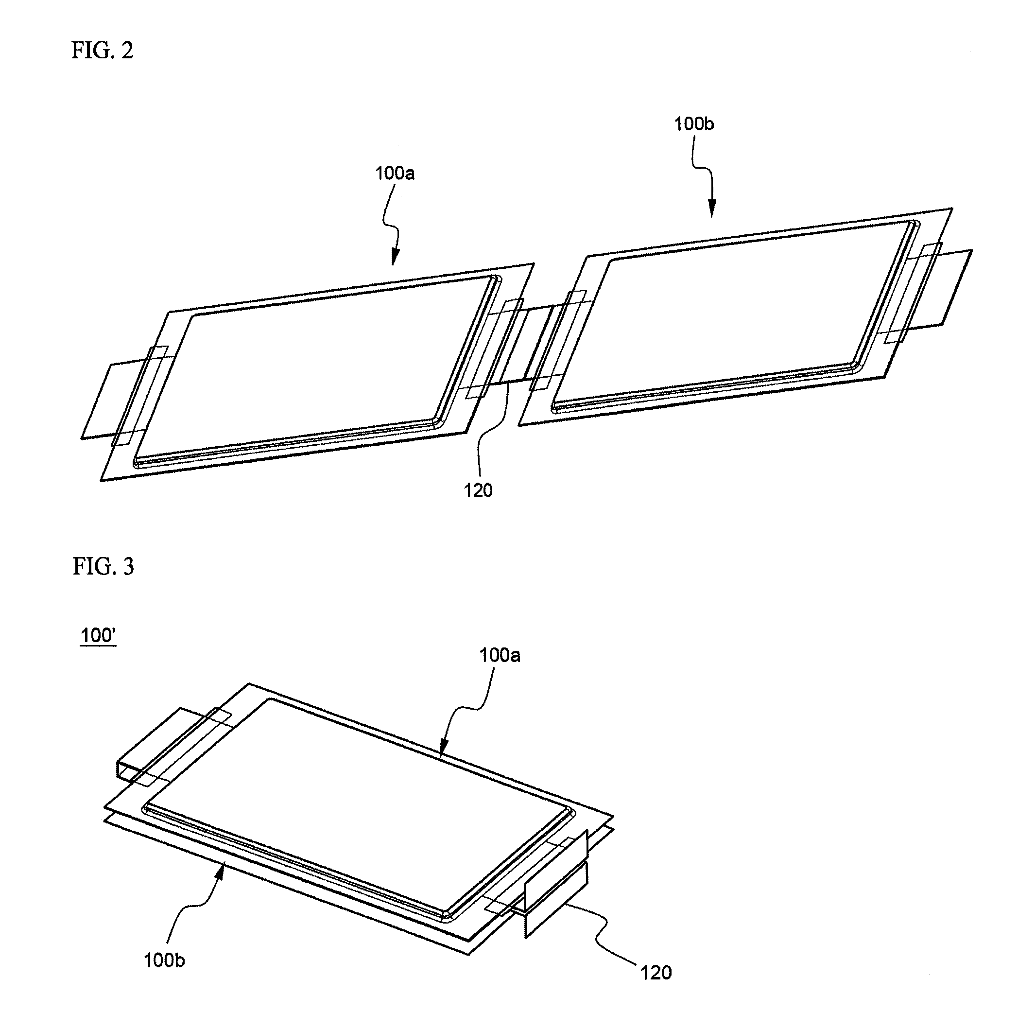
[0051]FIGS. 2 to 10 are views typically illustrating a process for assembling a battery module according to a preferred embodiment of the present invention, and FIGS. 11 to 13 are perspective views illustrating a process for assembling a middle- or large-sized battery pack using the battery module.

[0052]Referring first to FIG. 2, two pouch-shaped battery cells 100a and 100b are arranged in series in the longitudinal direction such that electrode terminals 120 of the battery cells 100a and 100b are successively adjacent to each other, the electrode terminals 120 of the battery cells 100a and 100b are coupled with each other by welding, and the battery cells 100a and 110b are folded such that the battery cells 100a and 110b overlap with each o...


PUM

PropertyMeasurementUnit
elastic couplingaaaaaaaaaa
shapeaaaaaaaaaa
shapesaaaaaaaaaa

Abstract

Disclosed herein is a battery module including two or more plate-shaped battery cells, as unit cells, constructed in a stacked structure in which electrode terminals of the battery cells are connected in series with each other and the electrode terminal connections are bent such that the battery cells are stacked, and a pair of high-strength cell covers for surrounding the outer surfaces of the battery cells when the cell covers are coupled with each other. The present invention has the effect of easily mounting a sensing unit that is capable of minimizing the weight and size of battery cells while effectively reinforcing the low mechanical strength of the battery cells and sensing the operation state of the battery cells to a battery module. In addition, the present invention has the effect of manufacturing the battery module by a simple assembly process without using a plurality of members for mechanical coupling and electrical connection, thereby decreasing the manufacturing costs of the battery module, and effectively preventing the battery module from being short-circuited or damaged during the manufacture or the operation of the battery module. Furthermore, the present invention has the effect of manufacturing a middle- or large-sized battery system having desired output and capacity using the battery module as a unit body.

Description

CROSS REFERENCE TO RELATED APPLICATIONS[0001]The present application is a national phase entry under 35 U.S.C. §371 of International Application No. PCT / KR2007 / 001022, filed Feb. 28, 2007, published in English, which claims priority from Korean Patent Application Nos. 10-2006-0020772, filed Mar. 6, 2006 and 10-2006-0045444, filed May 22, 2006. The disclosures of said applications are incorporated by reference herein.FIELD OF THE INVENTION[0002]The present invention relates to a battery module including plate-shaped battery cells having electrode terminals formed at the upper and lower ends thereof, and, more particularly, to a battery module including two or more battery cells constructed in a stacked structure in which electrode terminals of the battery cells are connected in series with each other and the electrode terminal connections are bent such that the battery cells are stacked, and a pair of high-strength cell covers for surrounding the outer surfaces of the battery cells e...

Claims


Application Information

Patent Timeline
Patent Type & Authority Patents(United States)
IPC IPC(8): H01M6/42H01M2/20H01M10/42H01M10/48H01M2/10H01M2/24H01M2/02H01M50/124H01M50/211H01M50/244H01M50/262H01M50/516H01M50/529H01M50/569
CPCH01M2/1077H01M2/0277H01M2/1061H01M2/206H01M10/425H01M10/486H01M2/0275H01M2/0287H01M2/10Y02E60/10H01M50/124H01M50/516H01M50/569H01M50/244H01M50/211H01M50/262
Inventor YANG, HEEKOOKYANG, JAE HUNLEE, JIN KYU
Owner LG ENERGY SOLUTION LTD
Why Eureka
Try Eureka