Phantom degrees of freedom for manipulating the movement of mechanical bodies

a technology of mechanical bodies and freedom, applied in the field of improved surgical and/or robotic devices, systems, and methods, can solve the problems of affecting the operation efficiency of the robot manipulator, the inability to achieve two orientational degrees of freedom within the workspace, and the inability to control the robot manipulator arms and/or tools

Active Publication Date: 2016-03-01
INTUITIVE SURGICAL OPERATIONS INC
View PDF19 Cites 54 Cited by
  • Summary
  • Abstract
  • Description
  • Claims
  • Application Information

AI Technical Summary

Problems solved by technology

However, only a relatively small number of surgeries currently use these techniques due to limitations in minimally invasive surgical instruments and techniques and the additional surgical training required to master them.
In such cases, controllers that are used to control the robotic manipulator arms and / or tools may become overconstrained.
For example, where the remote tool is a rigid endoscope extending through a minimally invasive aperture, two orientational degrees of freedom may not be available within the workspace (those associated with a tool wrist near an end effector, e.g., wrist pitch and yaw).
In practice, these mathematical problems can become tangible, resulting in a sluggish, unresponsive feel to the surgeon which is undesirable.
Further problems can arise when tools having different degrees of freedom are used with the same robotic surgical manipulator.
Even further problems can arise when using estimated joint positions to control tool movements in situations where input and output degrees of freedom differ.
Such situations may result in numerical errors being imposed into the joint position estimations resulting in undesired tool movements.

Method used


Image

  • Phantom degrees of freedom for manipulating the movement of mechanical bodies
  • Phantom degrees of freedom for manipulating the movement of mechanical bodies
  • Phantom degrees of freedom for manipulating the movement of mechanical bodies

Examples


first embodiment

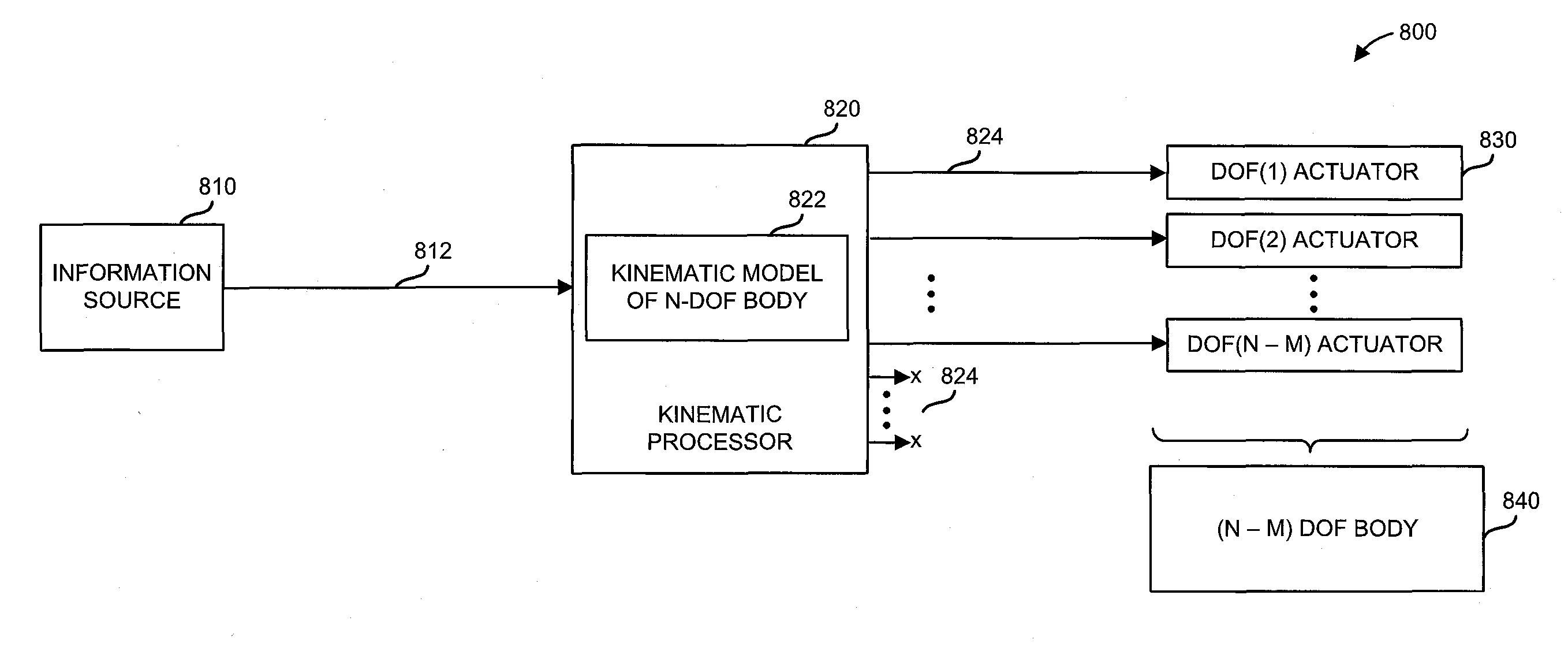
[0111]FIG. 10A is a block diagram showing a simplified system 1000 for controlling a manipulator assembly using an input device in accordance with a System 1000 includes an input device 1010, a controller 1020, and a manipulator assembly 1030. The input device 1010 may be similar to the information source 810 discussed with reference to FIG. 8, controller 1020 may be similar to the kinematic processor 820 discussed with reference to FIG. 8, and the manipulator assembly 1030 may be similar to the actuators and mechanical body 840 discussed with reference to FIG. 8. In one embodiment, the manipulator assembly 1030 includes a manipulator (e.g., manipulator 500) and / or a tool (e.g., tool 511). Manipulator assembly 1030 may have one or more manipulator kinematic degrees of freedom and, in some embodiments, may also or alternatively have one or more actuation degrees of freedom. Further, manipulator assembly 1030 may be operable to control the position of one or more end effectors (or, m...

second embodiment

[0116]FIG. 10B is a block diagram showing a simplified system 1001 for controlling a manipulator assembly using an input device in accordance with a System 1001 includes an input device 1010, a controller 1020, and a manipulator assembly 1030, which may be similar to those discussed with reference to FIG. 10A.

[0117]In accordance with this embodiment, the input device 1010 and controller 1020 are operable to control a greater number of kinematic degrees of freedom than the manipulator assembly 1030 has, similar to the embodiment discussed with reference to FIG. 10A. Further, the input device 1010 is operable to actuate a non-kinematic degree of freedom of the manipulator assembly 1030. For example, the input device 1010 may be operable to actuate a vacuum pressure associated with the manipulator assembly 1030.

[0118]Accordingly, in this embodiment, the input device 1010 includes six kinematic degrees of freedom 1012 as well as at least one actuation degree of freedom 1014, where the ...

third embodiment

[0121]FIG. 10C is a block diagram showing a simplified system 1002 for controlling a manipulator assembly using an input device in accordance with a System 1002 includes an input device 1010, a controller 1020, and a manipulator assembly 1030, which may be similar to those discussed with reference to FIG. 10A.

[0122]In accordance with this embodiment, the manipulator assembly 1030 has a number of kinematic degrees of freedom (e.g., eight), which includes at least one null space degree of freedom (e.g., three null space degrees of freedom), but still lacks at least one of the degrees of freedom necessary to fully define the position of an end effector associated with the manipulator assembly 1030. For example, although the manipulator assembly 1030 includes eight kinematic degrees of freedom including redundant degrees of freedom, it still lacks at least one independently controllable rotation or translation degree of freedom.

[0123]It should be recognized that when null space degrees...


PUM


Abstract

Methods, apparatus, and systems for controlling the movement of a mechanical body. In accordance with a method, desired movement information is received that identifies a desired motion of a mechanical body, the mechanical body having a first number of degrees of freedom. A plurality of instructions are then generated by applying the received desired movement information to a kinematic model, the kinematic model having a second number of degrees of freedom greater than the first number of degrees of freedom, each of the instructions being configured to control a corresponding one of the second number of degrees of freedom. A subset of the plurality of instructions are then transmitted for use in controlling the first number of degrees of freedom of the mechanical body.

Description

CROSS-REFERENCES TO RELATED APPLICATIONS[0001]This application claims the benefit of U.S. Provisional Application No. 61 / 683,495, filed Aug. 15, 2012, which is incorporated by reference herein in its entirety for all purposes.[0002]The present application is generally related to the following commonly-owned applications: U.S. Provisional Application No. 61 / 654,764 filed Jun. 1, 2012, entitled “Commanded Reconfiguration of a Surgical Manipulator Using the Null Space”, U.S. application Ser. No. 12 / 494,695 filed Jun. 30, 2009, entitled “Control of Medical Robotic System Manipulator About Kinematic Singularities;” U.S. application Ser. No. 12 / 406,004 filed Mar. 17, 2009, entitled “Master Controller Having Redundant Degrees of Freedom and Added Forces to Create Internal Motion;” U.S. application Ser. No. 11 / 133,423 filed May 19, 2005 (U.S. Pat. No. 8,004,229), entitled “Software Center and Highly Configurable Robotic Systems for Surgery and Other Uses;” U.S. application Ser. No. 10 / 957,0...

Claims


Application Information

Patent Timeline
Patent Type & Authority Patents(United States)
IPC IPC(8): B25J13/00B25J9/16
CPCB25J9/16B25J9/1689G05B2219/40195G05B2219/45123Y10S901/02A61B34/35A61B34/37
Inventor HOURTASH, ARJANG, M.AU, SAMUEL, KWOK, WAIBONNEAU, RAYMOND, A.DIOLAITI, NICOLAHINGWE, PUSHKARKERDOK, AMY, E.TURNER, MICHAEL
Owner INTUITIVE SURGICAL OPERATIONS INC
Why Eureka
Try Eureka