Dual chambered passenger airbag

a passenger airbag and dual chamber technology, applied in the direction of pedestrian/occupant safety arrangement, vehicle components, vehicular safety arrangements, etc., can solve the problems of difficult design of multi-chamber airbags, the design of the seat does not differentiate between these different regions, etc., to maximize the protection of adult occupants and minimize the risk

Active Publication Date: 2016-03-01
JOYSON SAFETY SYST ACQUISITION LLC
View PDF30 Cites 4 Cited by
  • Summary
  • Abstract
  • Description
  • Claims
  • Application Information

AI Technical Summary

Benefits of technology

[0010]In another aspect of the embodiments of the described herein, an airbag is provided including at least one panel defining an interior of the airbag, and a divider positioned in the interior so as to divide the interior into an upper chamber and a lower chamber. The airbag is structured to provide proportional restraint of a thoracic region of a vehicle occupant after activation of the airbag. In accordance with the present invention, the airbag divider is designed to maximize protection of adult occupants while minimizing the risk to young out-of-position occupants. Accordingly, the effective length of the divider is greater than or equal to at least 105% of the effective length of the airbag, thereby resulting in a desired trajectory upon deployment.

Problems solved by technology

However, these cushion designs do not differentiate between these different regions with regard to the stiffness or resistance of the various portions of the airbag to contact with each region.
Due to the differences in body part masses and the dynamics of contact between the occupant and the cushion, it has proven difficult to design a multi-chamber airbag which provides optimum protection for each portion of the body contacting the airbag.

Method used


Image

  • Dual chambered passenger airbag
  • Dual chambered passenger airbag
  • Dual chambered passenger airbag

Examples


example 1

Locating the Valve Mechanism(s)

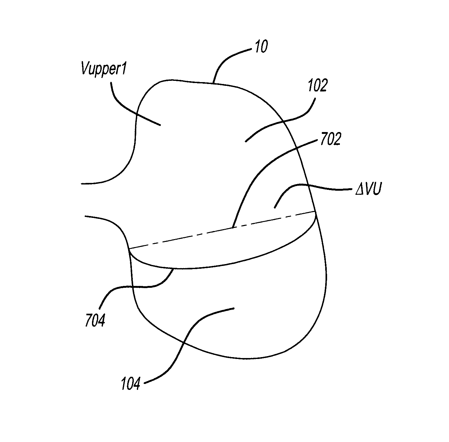
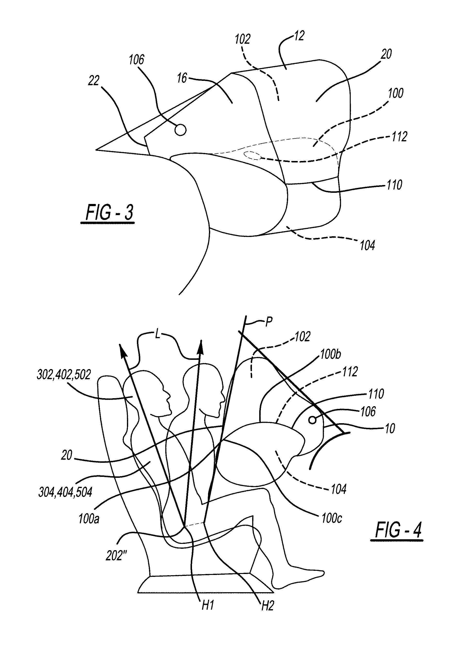
[0091]A passenger-side airbag of an occupant protection system is formed by iteratively considering the design variables P1, P2, D1, Ld, La, and Z3 in view of the specific interior of an automotive vehicle associated with the occupant protection system. The following steps are taken:[0092]1. Obtain a vehicle occupant seating drawing defining a centerline of normally-seated H-III adult male 50 percentile (AM50) and H-III adult female 5 percentile (AF05) ATDs.[0093]2. Begin defining the airbag / cushion profile by placing a fully chambered or deployed airbag profile in position for the normally-seated AM50 as shown in the vehicle drawing from step 1.[0094]3. Finalize the airbag / cushion profile by confirming the airbag profile for the forward-seated AF05 to make sure the overlap with regard to the AM50 is acceptable. If desired, minor adjustments may be made with confirmation by testing vis a vis the requirements of FMVSS208. With reference to FIG. 7, posit...

example 2

[0103]A passenger-side airbag was formed as per Example 1 wherein the arcuate length of Ld was 22 inches and the linear length of La was 19 inches. As such, the arcuate length of Ld was about 15% greater than the linear length of La.

example 3

[0104]A passenger-side airbag was formed as per Example 1 wherein the arcuate length of Ld was 21 inches and the linear length of La was 18 inches. As such, the arcuate length of Ld was about 16% greater than the linear length of La.


PUM

PropertyMeasurementUnit
total areaaaaaaaaaaa
vertical distanceaaaaaaaaaa

Abstract

An airbag 10 includes at least one panel 12 defining an interior 104 / 102 of the airbag, and a divider 100 positioned in the interior so as to divide the interior into an upper chamber 102 and a lower chamber 104. A valve mechanism 200 is operatively coupled to the divider 100 for restricting a flow of gases from the lower chamber 104 into the upper chamber 102. The valve mechanism 200 includes one or more valves 200 with a desired aggregate opening(s) and located in predetermined location(s) thereby affecting a designed inflation profile. The divider 100 has an arcuate length Ld, measured between two divider airbag attachment points 100d and 100a, greater than a corresponding linear horizontal airbag length La, measured between the same two attachment points. The passenger side airbag 10 for each unique vehicle is designed by iteratively reconciling the requirements of FMVSS208 with the present airbag design.

Description

CROSS-REFERENCE TO RELATED APPLICATIONS[0001]This application claims the benefit of U.S. Provisional Application Ser. No. 61 / 785,961, filed on Mar. 14, 2013, the disclosure of which is incorporated herein by reference in its entirety. This application is also a continuation-in-part of and co-owned U.S. application Ser. No. 14 / 192,812 having a filing date of Feb. 27, 2014.BACKGROUND OF THE INVENTION[0002]The present invention relates a passenger airbag, which is filled with gas during an emergency situation such as, for example, a frontal or side impact.[0003]Current airbag cushion designs may include multiple chambers and may incorporate an inter-chamber venting system that allows gas to flow from one chamber to another. These cushions are configured to rapidly contact a vehicle occupant when inflated, to limit movement of the passenger head, neck and thoracic regions. However, these cushion designs do not differentiate between these different regions with regard to the stiffness or...

Claims


Application Information

Patent Timeline
Patent Type & Authority Patents(United States)
IPC IPC(8): B60R21/233B60R21/239
CPCB60R21/233B60R21/239B60R2021/2395B60R2021/23324Y10T29/49826
Inventor ANDERSON, CHRISTOPHER, L.ZENG, SAMUEL
Owner JOYSON SAFETY SYST ACQUISITION LLC
Why Eureka
Try Eureka