
U-joint extracting tool and method of use therefor

a tool and u-joint technology, applied in the field of u-joint extraction tools, can solve the problems of exposing the joint and possibly adjacent items to damage, damage or injury, and other methods that may use a hammer or a pry bar are even more dangerous, so as to reduce effort and time

Inactive Publication Date: 2012-03-13
RUTHERFORD BRIAN
View PDF23 Cites 3 Cited by
  • Summary
  • Abstract
  • Description
  • Claims
  • Application Information

AI Technical Summary

Benefits of technology

[0013]In view of the foregoing disadvantages inherent in the prior art, it has been observed that there is need for a universal joint extraction tool that is compact, easy to use and that maximizes operator protection.
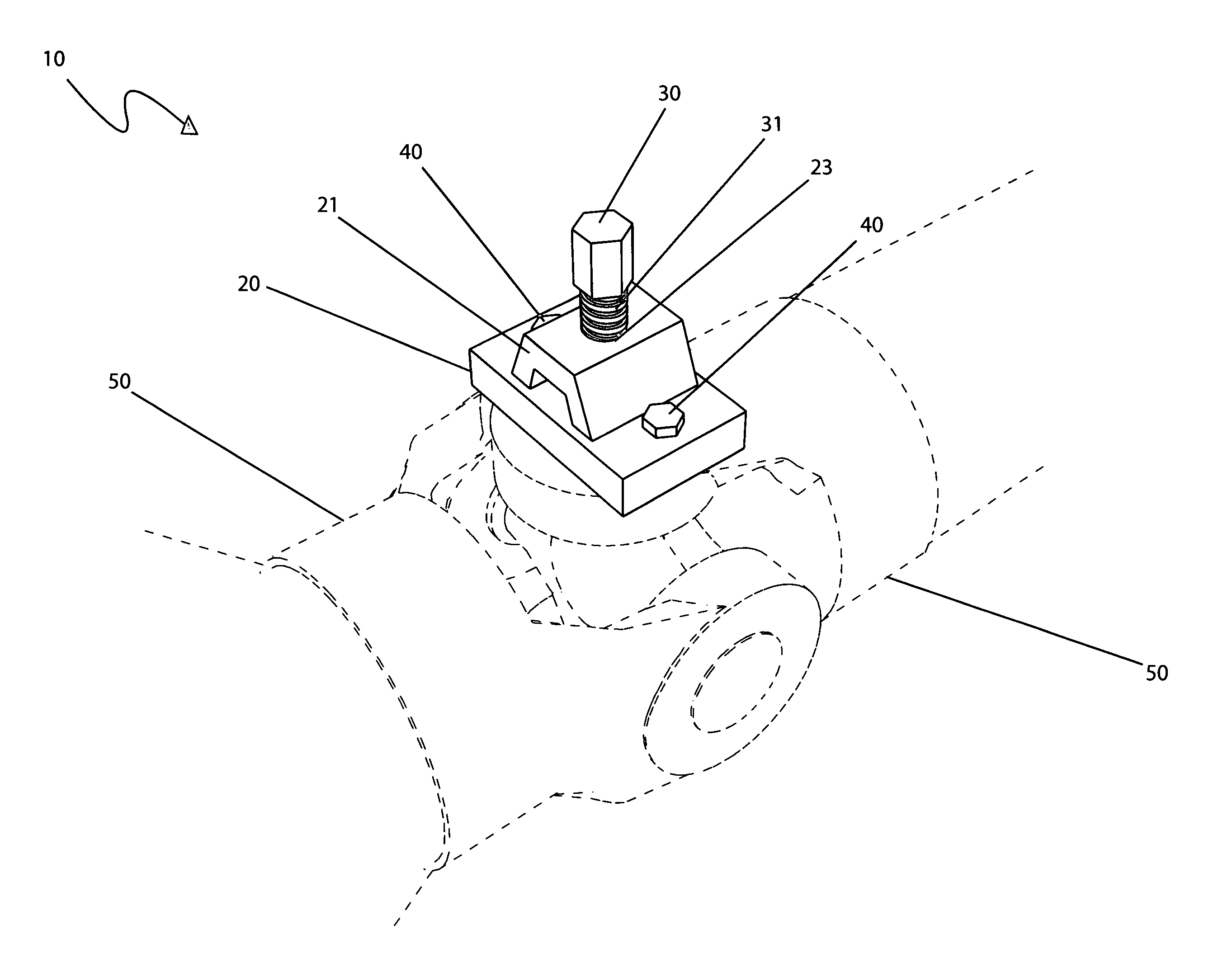
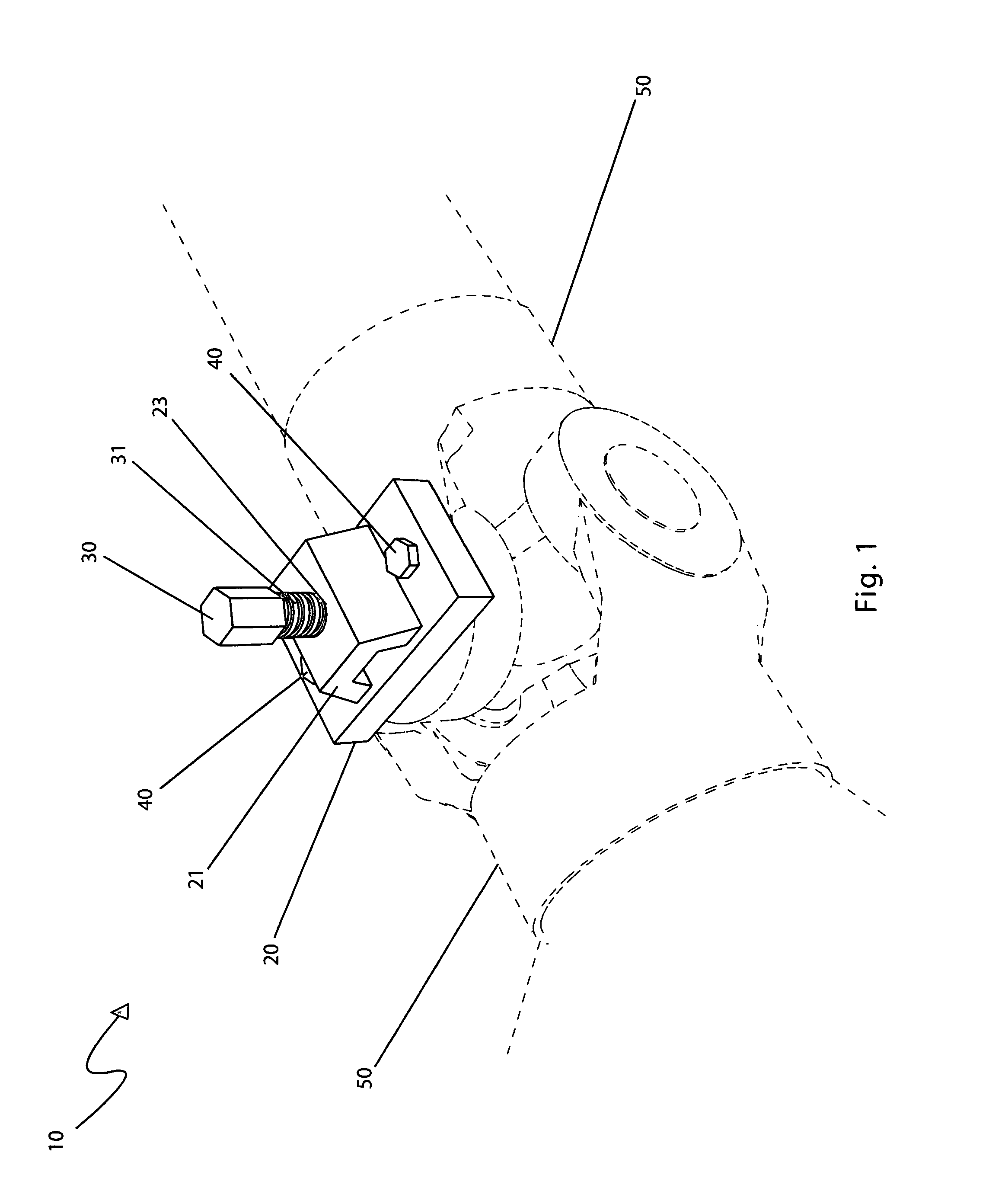
[0014]The universal joint extracting tool provides a convenient and easy method and method for heavy duty universal joint or Spicer® joint extraction.
[0017]The universal joint extracting tool facilitates the removal of the universal joint caps without slipping or repositioning itself while in use.
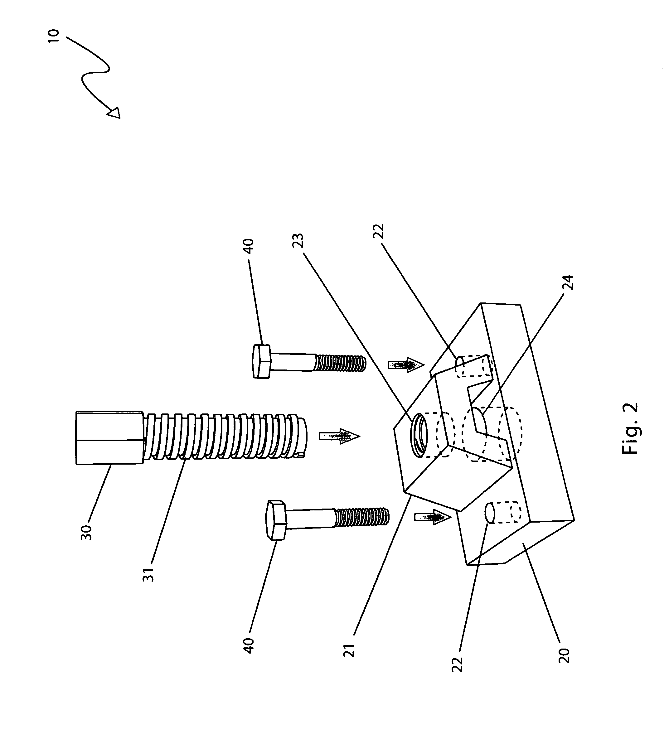
[0027]The universal joint extracting tool may be used by performing the following steps: exposing the threaded mounting holes on an existing heavy-duty universal joint by removing a single spot welded retainer cap plate using a grinder or other appropriate tool; aligning the mounting aperture portions of the invention with the existing cap bolt holes; installing the two (2) mounting bolts therethrough the mounting apertures and threadingly engaging said mounting bolts thereinto existing retainer cap bolt holes by turning said mounting bolts clockwise until tight using a wrench type tool; screwing the driver shaft into the driver aperture until said driver shaft contacts the heavy-duty universal joint shaft; pressing the universal joint cap, located on an opposite side, from the universal joint casting by applying sufficient torque to the hexagon feature in a clockwise direction using a wrench type tool; removing the device from the universal joint following extraction thereof by removing the two (2) mounting bolts; storing the device until needed again; and, benefiting from reduced effort and time required to extract heavy-duty universal joints using the present invention.

Problems solved by technology

However, many of these methods may subject the joint, and possibly adjacent items, to damage.
However, such presses are prone to slipping off and possibly causing damage or injury.
Other methods that may use a hammer or a pry bar are even more dangerous.
As those who have ever worked with heavy-duty joints will attest, replacing them with a punch and hammer requires a great deal of physical exertion and time spent ensuring that the positioning is correct.
Further, there is often times inadequate space to swing a hammer with the necessary force to remove the joint.
This patent does not appear to disclose a tool device and method for quickly and easily removing heavy duty universal joints for servicing.
This patent does not appear to disclose a tool device that bolts onto the universal joint and when manipulated quickly and easily removes a heavy duty universal joint.
This patent does not appear to disclose a tool device and method of using the tool device to quickly and easily removing heavy duty universal joints for servicing.
This patent does not appear to disclose a tool device that bolts onto the universal joint and does not use a hexagonal feature to displace the bearing cup.
This patent does not appear to disclose a tool device and method for quickly and easily removing heavy duty universal joints for servicing.
This patent does not appear to disclose a tool device that bolts onto the universal joint and when manipulated quickly and easily removes a heavy duty universal joint.
The prior art does not appear to disclose a removal tool device that bolts onto the universal joint and utilizes a to mounted hexagonal feature connected to a driver shaft to quickly, safely, and easily remove a bearing cup from a universal joint.

Method used


Image

  • U-joint extracting tool and method of use therefor
  • U-joint extracting tool and method of use therefor
  • U-joint extracting tool and method of use therefor

Examples


Embodiment Construction

[0032]The best mode for carrying out the invention is presented in terms of its preferred embodiment, herein depicted within FIGS. 1 and 2. However, the invention is not limited to the described embodiment and a person skilled in the art will appreciate that many other embodiments of the invention are possible without deviating from the basic concept of the invention, and that any such work around will also fall under scope of this invention. It is envisioned that other styles and configurations of the present invention can be easily incorporated into the teachings of the present invention, and only one particular configuration shall be shown and described for purposes of clarity and disclosure and not by way of limitation of scope.

[0033]The terms “a” and “an” herein do not denote a limitation of quantity, but rather denote the presence of at least one of the referenced items.

[0034]The present invention describes a device and method for a universal joint extracting tool (herein desc...


PUM

PropertyMeasurementUnit
Lengthaaaaaaaaaa
Shapeaaaaaaaaaa

Abstract

An apparatus that aids in the removal of heavy-duty universal joints or Spicer® joints is herein disclosed. The apparatus is comprised of a metal plate approximately four (4) inches long and two-and-a-half (2½) inches wide. Two (2) outer apertures in the metal plate attach to the corresponding retaining bolt holes on an existing universal joint. The inner hole has a driver shaft driven by a three-quarter (¾) inch hex fitting. This driver shaft facilitates the removal of the joint caps of the universal joint. The apparatus is secure and will not slip or reposition itself while in use. When finished, the apparatus is removed from the drive shaft. The use of the apparatus allows for the removal of heavy-duty universal joints in an efficient manner.

Description

FIELD OF THE INVENTION[0001]The present invention relates generally to a tool for the extraction of U-joints in a quick and easy manner.BACKGROUND OF THE INVENTION[0002]About 130,000 companies in the U.S. are involved primarily in auto repair, with combined annual revenue of $65 billion. Aside from dedicated repair establishments, 45,000 gas stations, 24,000 new car dealerships, and branches of department store chains provide some car repair work. Thus, there is a large demand for automotive and industrial vehicle repair tools that are easy to use and offer time savings.[0003]Heavy-duty universal joints, also known as Spicer® series, are commonly used on over-the-road vehicles and for industrial and off-highway applications. They are designed for long life at moderate torque levels, though they are capable of withstanding high momentary torques such as those encountered in starting a load or moving a vehicle. As effective as such joints are they do require periodic replacement or ma...

Claims


Application Information

Patent Timeline
IPC IPC(8): B23P17/00
CPCB25B27/062Y10T29/53943Y10T29/53883Y10T29/53891Y10T29/53826Y10T29/53852Y10T29/49698
Inventor RUTHERFORD, BRIAN
Owner RUTHERFORD BRIAN
Learn More