Permanent magnet arrangement for an electrical machine

a permanent magnet and electrical machine technology, applied in the direction of rotating magnets, synchronous machines with stationary armatures, dynamo-electric machines, etc., can solve the problems of prone to fracture and corrosion, brittle permanent magnet material from which the magnet pole is formed, etc., to achieve the effect of assisting with the control of electrical stability

Inactive Publication Date: 2011-11-22
GE ENERGY POWER CONVERSION TECH
View PDF14 Cites 4 Cited by
  • Summary
  • Abstract
  • Description
  • Claims
  • Application Information

AI Technical Summary

Benefits of technology

[0017]The permanent magnet material from which the magnet pole is formed is very brittle and prone to fracture and corrosion. This is particularly the case when the permanent magnet material is high-energy-product or rare earth magnet material. The sleeve provides both mechanical and environmental protection for the permanent magnet material and contains the permanent magnet material in the event that the material forming the magnet pole fractures or disintegrates. It also protects the permanent magnet material from external contaminants, thereby minimising the risk of corrosion.
[0018]The sleeve is not, however, fixed to the magnet carrier and this significantly simplifies the assembly of the permanent magnet arrangement by allowing straightforward insertion of one or more pole assemblies into the sleeve, without the need to secure the sleeve to the magnet carrier. The sleeve is, however, held securely in place by virtue of the fact that it is clamped against the support structure by the magnet carrier when the magnet carrier is secured to the support structure to fix the pole assembly to the support structure.
[0021]The sleeve may fully contain the magnet pole. This maximises the mechanical and environmental protection provided by the sleeve. For example, the permanent magnet arrangement may include closure means at the ends of the sleeve to thereby provide full encapsulation of the magnet pole. The closure means may comprise caps which are secured to the ends of the sleeve, for example by welding, brazing, bonding, clipping or using mechanical fixings. The closure means may alternatively comprise sealing material.
[0022]The magnet carrier is preferably releasably secured to the support structure to releasably fix the pole assembly to the support structure. This facilitates removal of the pole assembly from the support structure of the permanent magnet arrangement. Such removal is desirable to permit repair or replacement of the pole assembly.
[0029]The permanent magnet arrangement may include filler material inside the sleeve. The filler material fills any voids that may be present between the pole assembly and the sleeve and may provide the magnet pole with enhanced mechanical and environmental protection, in addition to the primary protection that is provided by the sleeve. The filler material is preferably a non-hardening elastomer. The filler material may be a non-metallic filler material such as epoxy resin, polymers such as polyurethane and polyesters, and vacuum impregnated fibres or felt.
[0032]In typical embodiments, the permanent magnet arrangement comprises a plurality of the aforesaid pole assemblies, each fixed to the support structure, and a plurality of sleeves each containing the magnet pole and at least part of the magnet carrier of a respective pole assembly. When the sleeves of the pole assemblies are made of an electrically conductive material, they may be connected together at their ends to form a damper cage. This may assist with the control of the electrical stability of an electrical machine in which the permanent magnet arrangement is installed.

Problems solved by technology

The permanent magnet material from which the magnet pole is formed is very brittle and prone to fracture and corrosion.

Method used


Image

  • Permanent magnet arrangement for an electrical machine
  • Permanent magnet arrangement for an electrical machine
  • Permanent magnet arrangement for an electrical machine

Examples


first embodiment

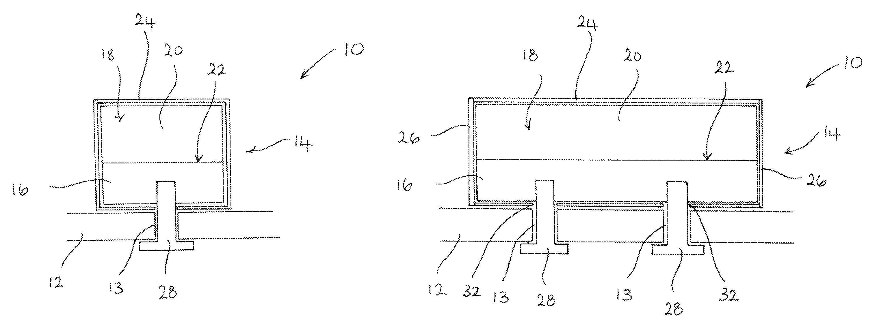
[0042]Referring initially to FIGS. 1 and 2, a permanent magnet arrangement 10 for an electrical machine comprises a support structure 12 including a plurality of apertures 13 and a pole assembly 14 fixed to the support structure 12. The support structure 12 is capable of carrying magnetic flux and is typically the rotor of an electrical machine. The rotor may be a cylindrical rotor of a radial flux machine, a disc rotor of an axial flux machine or a linear rotor (i.e. a translator) of a linear machine.

[0043]The pole assembly 14 comprises a generally elongate magnet carrier 16 made of magnetic material, such as steel, and a magnet pole 18 comprising one or more pieces of permanent magnet material 20. The magnet pole 18 is bonded to a surface 22 of the magnet carrier 16 but, as indicated above, the magnet pole 18 may be secured to the surface 22 of the magnet carrier 16 by any suitable means.

[0044]The permanent magnet arrangement 10 comprises a protective sleeve 24 into which the pole...

second embodiment

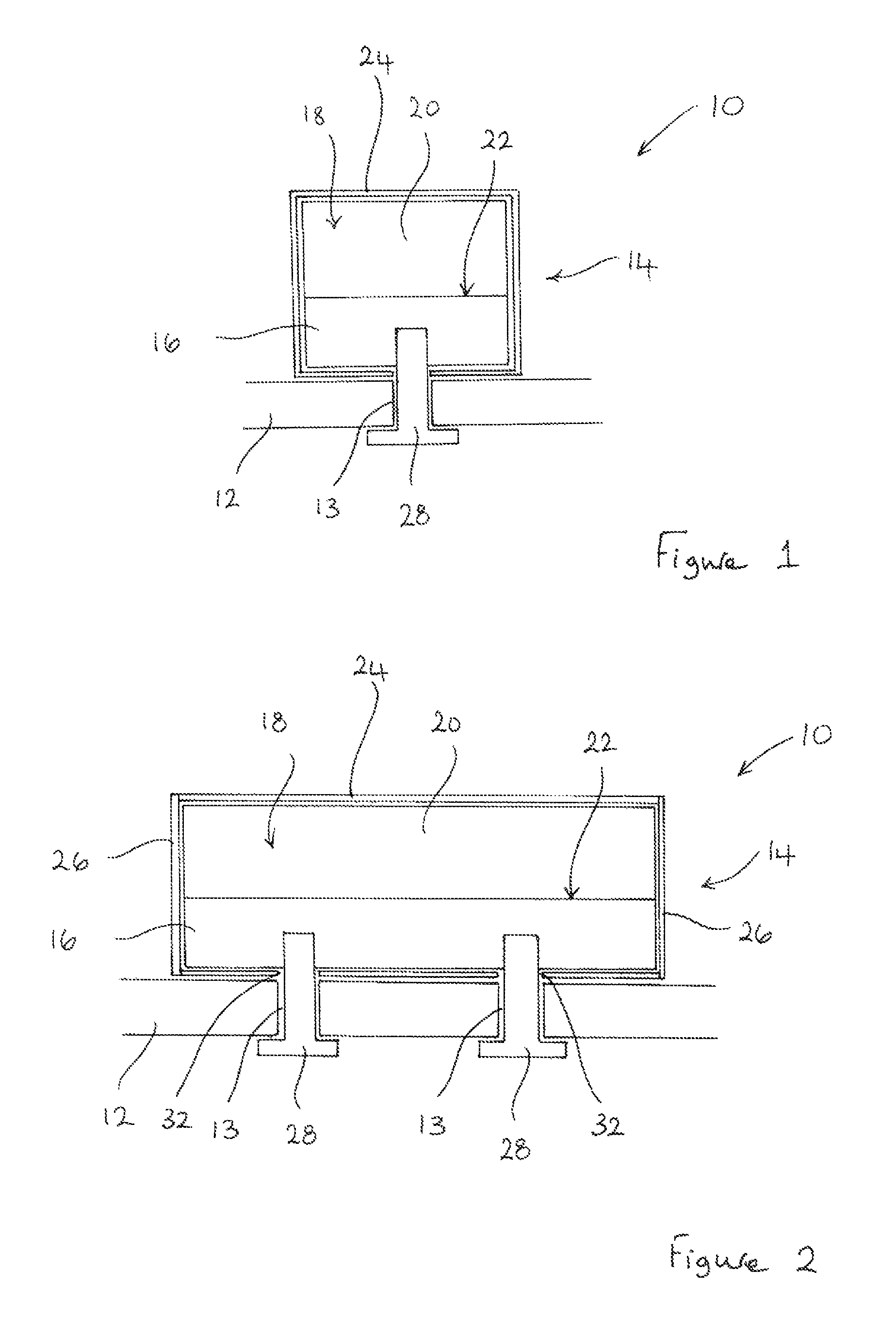
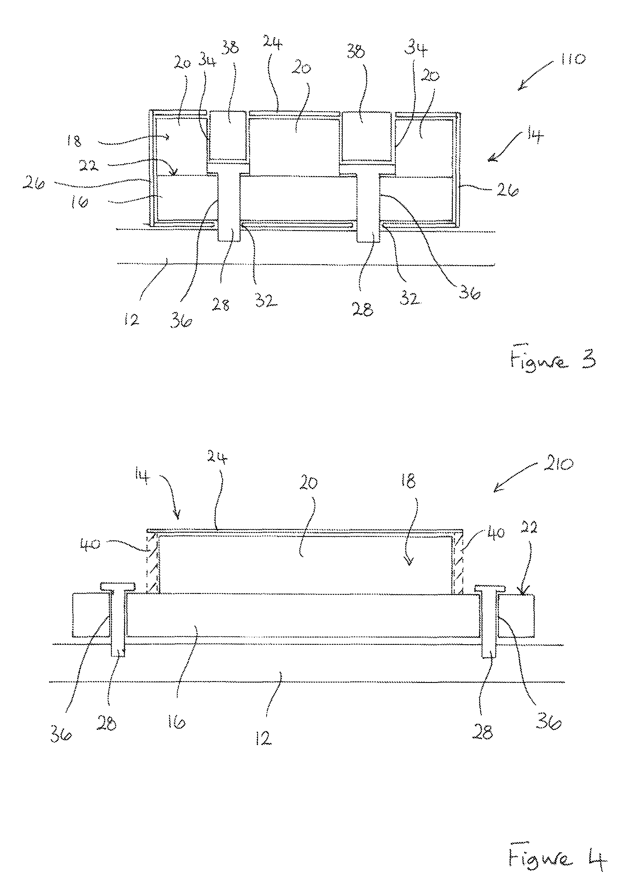
[0049]FIG. 3 illustrates a permanent magnet arrangement 110 which is similar to the permanent magnet arrangement illustrated in FIGS. 1 and 2 and in which corresponding features are designated using corresponding reference numerals.

[0050]In the permanent magnet arrangement 110, the pole assembly 14 comprises a plurality of pieces of permanent magnet material 20 secured to the surface 22 of the magnet carrier 16. The individual pieces of permanent magnet material 20 are spaced apart to define openings 34 for receiving the mechanical fixings 28. The mechanical fixings 28 extend though apertures 36, 32 in both the magnet carrier 16 and the protective sleeve 24 to enable the mechanical fixings 28 to engage the support structure 12. The mechanical fixings 28 thus cooperate with both the magnet carrier 16 and the support structure 12 so that they fix the magnet carrier 16, and hence the pole assembly 14, to the support structure 12. The protective sleeve 24 is again clamped to the support...

third embodiment

[0053]FIG. 4 illustrates a permanent magnet arrangement 210 which is generally similar to the permanent magnet arrangement illustrated in FIGS. 1 and 2 and in which corresponding features are designated using corresponding reference numerals.

[0054]In the permanent magnet arrangement 210, the magnet pole 18 is fully contained within the protective sleeve 24 to provide it with the necessary mechanical and environmental protection. However, the ends of the magnet carrier 16 extend from the ends of the protective sleeve 24 and are, thus, exposed. It is those exposed ends of the magnet carrier 16 that are secured to the support structure 12 by the mechanical fixings 28.

[0055]In this particular embodiment, the use of end caps 26 to close the ends of the protective sleeve 24 may be inappropriate. Closure means in the form of sealant material 40 may instead be used to close the ends of the protective sleeve 24 to maximise the mechanical and environmental protection provided to the magnet po...


PUM


Abstract

A permanent magnet arrangement for an electrical machine comprises a support structure for carrying magnetic flux and a pole assembly fixed to the support structure. The pole assembly comprises a magnet pole comprising at least one piece of permanent magnet material, and a magnet carrier on which the magnet pole is mounted and which provides a magnetic flux path between the magnet pole and the support structure. The permanent magnet arrangement further comprises a sleeve containing the magnet pole and at least part of the magnet carrier. The magnet carrier is secured to the support structure to fix the pole assembly to the support structure and the sleeve is clamped to the support structure by the magnet carrier. A method for assembling the permanent magnet arrangement is also described.

Description

FIELD OF THE INVENTION[0001]The present invention relates generally to a permanent magnet arrangement for an electrical machine. Embodiments of the present invention are concerned in particular with a permanent magnet arrangement in which one or more pole assemblies are releasably fixed to a support structure such as a rotor. The present invention also relates to a method for assembling a permanent magnet arrangement for an electrical machine.BACKGROUND OF THE INVENTION[0002]The use of high-energy-product permanent magnets (also known as rare earth magnets) in electrical machines is becoming more prevalent, especially in large-diameter low-speed permanent magnet motors and generators. Due to the high magnetic forces that are produced by these magnets and the highly brittle nature of the magnetic material and its susceptibility to corrosion if not suitably protected, their installation to form permanent magnet arrangements presents some difficulties.[0003]A number of arrangements hav...

Claims


Application Information

Patent Timeline
Patent Type & Authority Patents(United States)
IPC IPC(8): H02K21/12
CPCH02K41/031H02K1/278
Inventor CLARK, PAUL EATON
Owner GE ENERGY POWER CONVERSION TECH
Why Eureka
Try Eureka