Electric motor and electric power steering device using same

a technology of electric power steering and electric motor, which is applied in the direction of control/drive circuit, mechanical energy handling, mechanical equipment, etc., can solve the problems of reducing measurement accuracy, affecting the operation of magnetic sensors, and reducing the degree of corrosion resistance of the first and second frames, so as to reduce noise, reduce the risk of settling or reducing the risk of settling. , the effect of reducing the risk of settling

Active Publication Date: 2017-11-23
DENSO CORP
View PDF0 Cites 5 Cited by
  • Summary
  • Abstract
  • Description
  • Claims
  • Application Information

AI Technical Summary

Benefits of technology

[0021]As apparent from the above discussion, the biasing member works to press the shaft in the axial direction thereof, thereby minimizing noises arising from mechanical vibration or resonance of the rotor in the axial direction thereof. The biasing member is, as described above, made of austenite stainless steel, thus minimizing a risk of settling thereof or a loss of a spring load produced thereby when subjected to high temperatures.
[0022]The coating covers the outer surfaces of the first frame and the second frame, thus increasing a degree of resistance of the first and second frames to corrosion thereof.
[0023]The coating-unoccupied area occupies at least the portion of the surface of the first frame or the second frame which faces the biasing member, thereby causing the surface of the first frame or the second frame which is made of metallic material containing aluminum to sacrificially corrode to minimize the risk of the stress corrosion cracking in the biasing member.

Problems solved by technology

In the case where the biasing member of the electric motor is made of iron, it lead to a risk of settling thereof or a loss of a spring load produced thereby when subjected to high temperatures.
In the case where the electric motor has a magnet attached to an end of the output shaft to measure, using a magnetic sensor, a magnetic flux produced by the magnet as indicating an angular position of the rotor of the electric motor, there is a risk that the biasing member made of metallic material is magnetized, which results in a disturbance to the operation of the magnetic sensor, thus leading to a decreased measurement accuracy thereof.
The use of the austenite stainless steel for making the biasing member, however, encounters drawbacks in that residual stress remaining in the biasing member after produced or stress exerted on the biasing member when compressed may accelerate cracking due to corrosion thereof (i.e., stress corrosion cracking).
However, when the electric motor is installed on a lower portion of the body of the vehicle, it will lead to a risk that the frame become eroded by splashing with water.

Method used


Image

  • Electric motor and electric power steering device using same
  • Electric motor and electric power steering device using same
  • Electric motor and electric power steering device using same

Examples


first embodiment

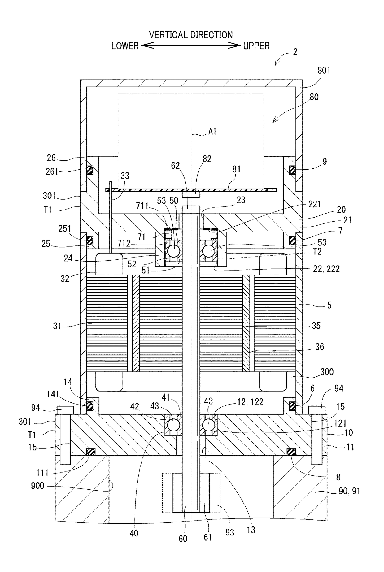
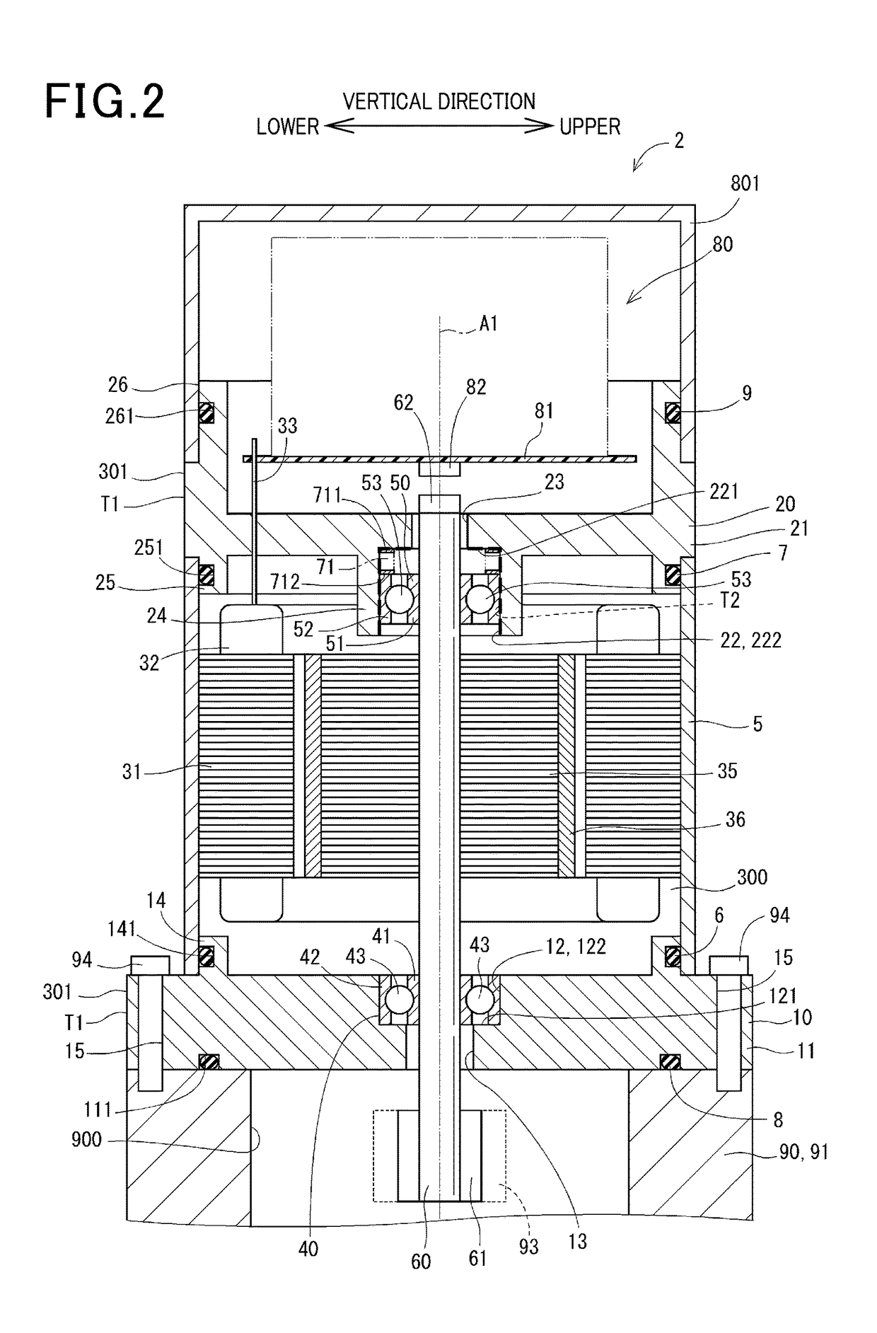
[0036]FIG. 2 illustrates the electric motor 2 according to the first embodiment. The electric motor 2 is supplied with electric power to produce torque and used in, for example, an electric power-steering device mounted in vehicles, such as automobiles, to assist a vehicle operator in turning the steering wheel.

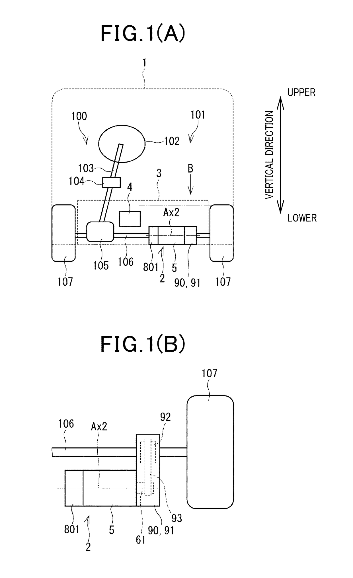
[0037]FIG. 1(A) illustrates an entire structure of the steering system 100 equipped with the electric power steering device 101. The electric power steering device 101 is equipped with the torque sensor 104 mounted on the steering shaft 103 connecting with the steering wheel 102. The torque sensor 104 works to measure a degree of steering torque exerted by an operator or a driver of the vehicle 1 on the steering shaft 103 through the steering wheel 102.

[0038]The steering shaft 103 has the pinion gear 105 mounted on an end thereof. The pinion gear 105 meshes with the rack shaft 106. The rack shaft 106 has a pair of wheels 107 secured to ends thereof through a tie rod to be rot...

second embodiment

[0115]FIG. 5 illustrates the electric motor 2 according to the second embodiment which is different from the first embodiment in that it is not equipped with the control unit 80 and the cover 801. The same reference numbers as employed in the first embodiment will refer to the same parts.

[0116]The second frame 20 does not have the second hole 23 and the cylinder 26 formed therein.

[0117]The shaft 60 has the first end which is farther away from the pulley 61 is located at a given distance from the second bottom wall 221 in the lengthwise direction of the shaft 60. The electric motor 2 is not equipped the magnetic 62 mounted on the first end of the shaft 60.

[0118]The coating-unoccupied area T2, as indicated by a thick broken so line in FIG. 5, lies at a portion of the outer surface of the second frame 20 which is occupied by the second bottom wall 221 and the second inner wall 222. In other words, the inner surface of the second recess 22 entirely has the coating-unoccupied area T2.

[01...

third embodiment

[0122]FIG. 6 illustrates the electric motor 2 according to the third embodiment which is different in layout of the biasing member 71 from the first embodiment.

[0123]The first bearing 40 and the first bottom wall 121 define an annular chamber therebetween. The biasing member 71 is mounted in the annular chamber between the first bottom wall 121 and the first bearing 40 and exert spring load on the shaft 60 through the first bearing 40, thereby pressing the shaft 60 in the lengthwise direction toward the second bearing 50.

[0124]Specifically, the biasing member 71 is compressed in the axial direction thereof (i.e., the first bearing 40) and mounted between the first bottom wall 121 and the first bearing 40. The biasing member 71, as can be seen in FIG. 6, has the end 711 placed in contact with the first bottom wall 121 and the end 712 placed in contact with one of opposed ends of the first outer cylinder 42 which faces the first bottom wall 121, so that it biases the first outer cylin...


PUM


Abstract

An electric motor is provided which is designed to minimize a risk of corrosion or stress corrosion cracking of parts thereof and reduce mechanical vibration or noise. The electric motor includes an output shaft, a bearing which retains the output shaft, a frame, and a biasing member. The biasing member is made of austenite stainless steel and disposed between the bearing and a bottom wall of a bearing housing to elastically press the output shaft in a lengthwise direction thereof for eliminating mechanical noise arising from vibration of a rotor. The frame has a coating formed on an outer surface thereof for avoiding erosion thereof. The coating is not formed at least on a portion of the frame which faces the biasing member in order to induce sacrificial corrosion of the frame, which decelerates the corrosion of the biasing member to eliminate a risk of the stress corrosion cracking thereof.

Description

CROSS REFERENCE TO RELATED DOCUMENT[0001]The present application claims the benefit of priority of Japanese Patent Application No. 2016-102315 filed on May 23, 2016, the disclosure of which is incorporated herein by reference.BACKGROUND1 Technical Field[0002]This disclosure relates generally to an electric motor and an electric power steering device using the same.2 Background Art[0003]Japanese Patent First Publication No. 2009-201255 teaches an electric motor which is used as an actuator for an electric power steering device of an automotive vehicle and equipped with a biasing member which urges an output shaft of the electric motor in an axial direction thereof. Specifically, the output shaft is retained at ends thereof by a first bearing and a second bearing. The biasing member urges the first bearing toward the second bearing, thereby pressing the output shaft in the axial direction thereof to minimize noise arising from mechanical vibration or resonance of a rotor of the electr...

Claims


Application Information

Patent Timeline
Patent Type & Authority Applications(United States)
IPC IPC(8): H02K5/173F16C33/44H02K5/06F16C33/82H02K5/128F16C33/38F16C33/56F16C33/76H02K5/16
CPCH02K5/1732H02K5/06H02K5/128F16C33/82F16C33/38H02K5/16H02K5/173F16C33/76F16C33/565F16C33/445F16C19/06F16C19/54F16C25/083F16C2380/26H02K5/10H02K5/24H02K7/1004H02K11/33
Inventor TOMIZAWA, HIROKIISOGAI, KOJI
Owner DENSO CORP
Why Eureka
Try Eureka