
Vehicle washing machine

a technology for washing machines and vehicles, applied in the direction of vehicle exterior cleaning apparatus, cleaning process and apparatus, cleaning apparatus, etc., can solve problems such as subject to damage, and achieve the effects of minimizing collision risk, minimizing corrosion risk, and minimizing collision risk

Inactive Publication Date: 2005-02-22
ECOJET SYST
View PDF28 Cites 5 Cited by
  • Summary
  • Abstract
  • Description
  • Claims
  • Application Information

AI Technical Summary

Benefits of technology

The present invention provides an improved vehicle washing system of the general type which does not contact the vehicle and is adapted to move relative to a vehicle disposed stationary in a washroom or bay.
In accordance with one aspect of the present invention a moveable vehicle wash system is provided which is configured to be supported on opposed linear support rails mounted within a wash bay in such a way as to minimize the risk of collision between the wash system and a vehicle as the vehicle is driven into and out of the wash bay. The wash system includes a frame which is mounted on the opposed parallel support rails a suitable height above the vehicle driveway surface so as to minimize the chance of collision with a vehicle as it is driven into and out of the wash bay.
In accordance with another aspect of the invention a vehicle wash system is provided which includes a frame comprising a bridge-like structure spanning a wash bay driveway and which is enclosed in a shroud or enclosure formed of plural shell-like cover members. The enclosure is pressurized with low pressure dry and heated air to minimize the risk of corrosion to the working parts of the system and to improve all-weather operating capability of the system, particularly at ambient temperatures below the freezing point for water.
In accordance with another aspect of the invention, a vehicle wash system is provided with a bridge-like frame structure which is supported on spaced apart elongated guide rails and includes all of the system drive mechanism and opposed moveable wash nozzle support arms supported substantially above a wash bay driveway and configured to be substantially out of the way with respect to a vehicle passing into the wash bay so as to minimize the chance of collision with a vehicle to be washed and damage to the drive mechanism. Moreover, the arrangement of opposed pivotable support arms for the washing nozzles is such that the system requires minimal linear reversible travel along the guide rails in order for the system to provide a complete washing cycle covering both sides and both ends of a vehicle. Still further, the frame construction for the vehicle wash system is particularly stiff and stable in operation.
In accordance with still another aspect of the invention, a vehicle wash system is provided with opposed moveable support arms for supporting an array of spray nozzles for spraying wash fluids including surfactant solutions, vehicle appearance enhancing chemicals and rinse water on a vehicle as the system moves relative to the vehicle. Wash fluids are conveyed to the spray nozzles through passages formed in spaced apart structural members of the support arms. A unique array of spray nozzles is mounted on the opposed support arms and operably connected to a drive mechanism which is operable to selectively rotate or oscillate the spray nozzles. The nozzle drive mechanism is also operable to position the support arms in proximity to vehicles of various sizes to more effectively clean the vehicle during a wash cycle.
The present invention also provides a vehicle washing system having an improved configuration for connection to sources of washing fluids, produces complex washing functions includes a relatively uncomplicated mechanical structure, includes a configuration of moveable nozzle support arms which provide for integral fluid conducting passages as well as passages for the routing of electrical conductors and other fluid conduits, as needed, and a drive mechanism for traversing the system linearly along opposed elevated support and guide rails.

Problems solved by technology

However, prior art systems of this type have been configured such that they are subject to damage by vehicles which enter the wash bay improperly and collide with certain components of the system.

Method used


Image

  • Vehicle washing machine
  • Vehicle washing machine
  • Vehicle washing machine

Examples


Embodiment Construction

In the description which follows like parts are marked throughout the specification and drawing with the same reference numerals respectively. The drawing figures are not necessarily to scale and certain features may be shown in generalized or schematic form in the interest of clarity and conciseness.

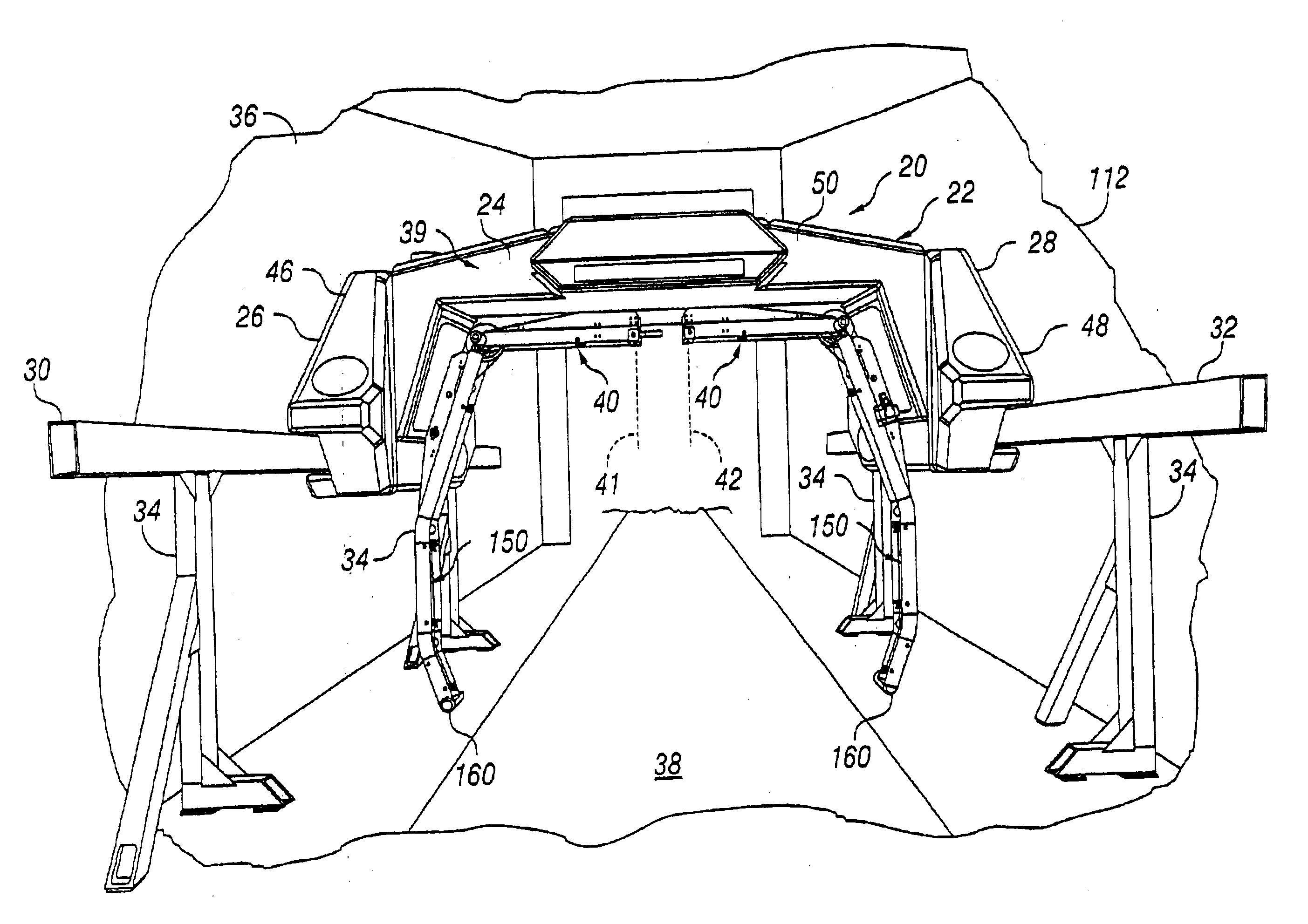
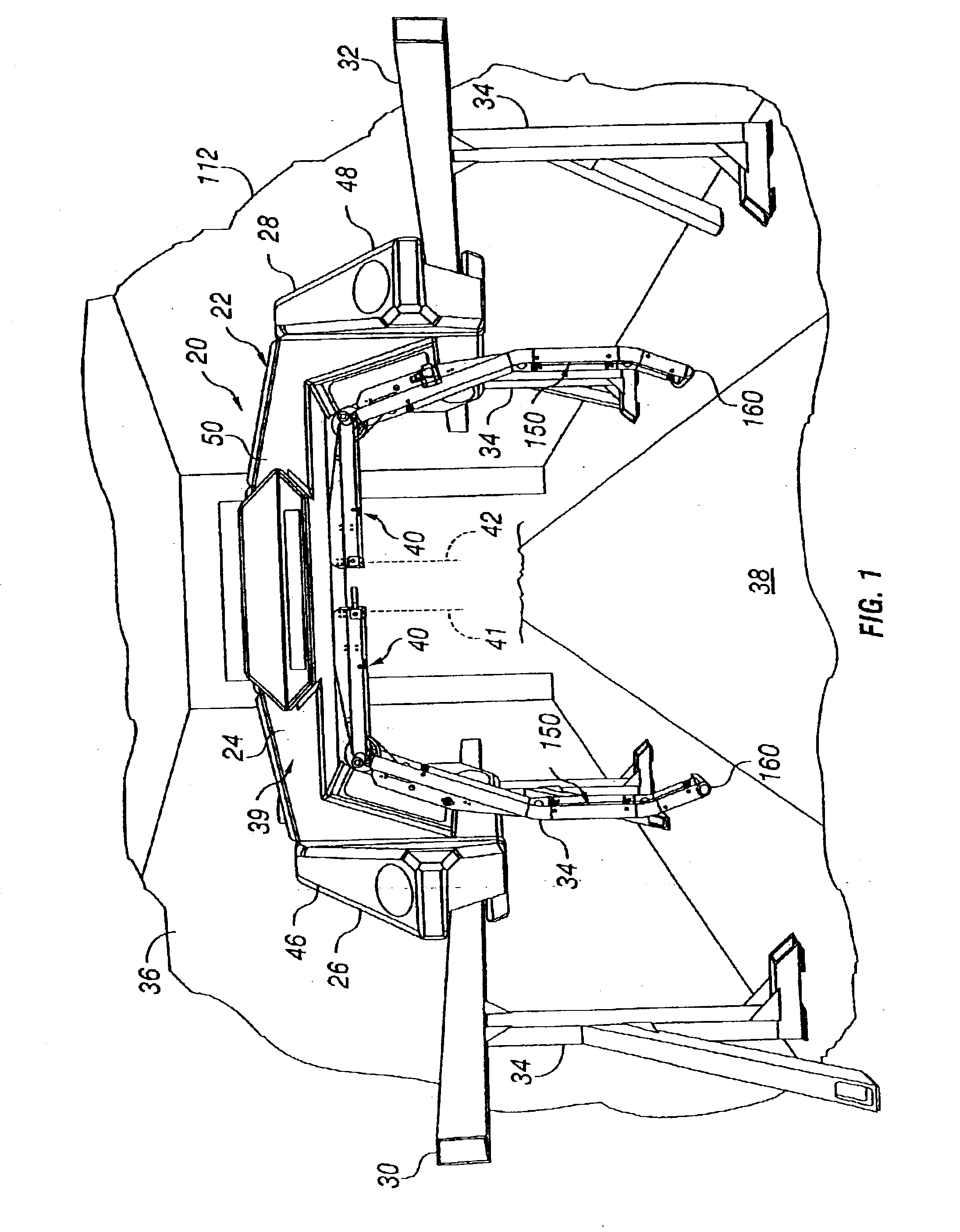
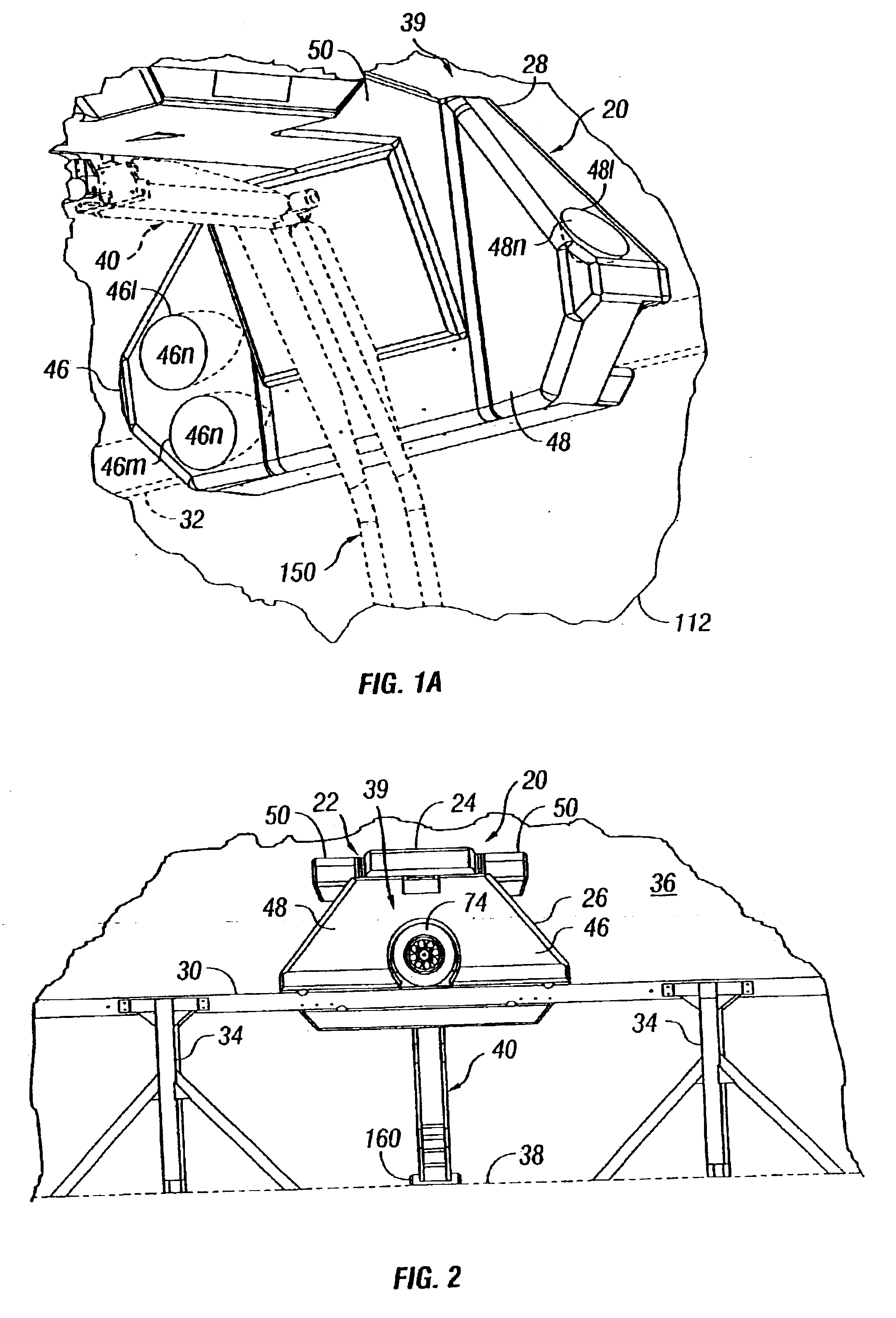
Referring to FIGS. 1 and 2, a vehicle washing system in accordance with the present invention is illustrated and generally designated by the numeral 20. The washing system 20 is characterized by a linearly traversable frame 22 comprising a bridge section 24 and opposed support sections 26 and 28, see FIG. 3 also. The frame 22, including support sections 24, 26 and 28, is adapted for linear reciprocating movement along opposed, generally rectangular cross section, guide and support rails 30 and 32, FIG. 1, which are mounted on suitable support legs 34, spaced apart within a wash room or wash bay 36, also as shown in FIG. 1. Wash room or bay 36 includes a vehicle driveway 38 into which a ...


PUM


Abstract

An automotive vehicle washing system includes a frame comprising a bridge member end opposed and support sections mounted for linear reciprocating movement on spaced apart support rails. Pivoting washing nozzle support arms are mounted on the bridge section and are interconnected by a drive motor and drive pulleys to move in opposite directions to wash the sides and opposite ends of a vehicle. Each arm includes movable arm sections supporting spaced apart nozzle assemblies which may move toward each other or away from each other to size a vehicle according to its width. Each arm includes opposed elongated beam members which also provide fluid conducting passages for conducting washing fluids to the nozzle assemblies. Certain ones of the nozzle assemblies are drivenly connected to an oscillating servomotor. The servomotor is also used to position the pivoting arm sections through a lost motion coupling and a gear drive unit.

Description

FIELD OF THE INVENTIONThe present invention pertains to an automotive vehicle washing system including opposed remotely controlled spray nozzle support arms mounted for pivotal movement on a frame which traverses along opposed support rails to carry out a vehicle washing cycle.BACKGROUND OF THE INVENTIONAutomotive vehicle washing systems of various types are known. Two basic systems have been developed, one comprising so called contact types wherein brushes or pads come into physical contact with the vehicle body to perform the washing function. The second type of system widely used is commonly referred to in the art as non-contact or touchless systems. Still further, so-called tunnel or drive through washing systems of both types are well known as well as so-called rollover systems wherein the vehicle remains stationary in the wash bay and the system moves with respect to the vehicle to perform the washing operation.Non-contact or touchless type washing systems, which move with res...

Claims


Application Information

Patent Timeline
Patent Type & Authority Patents(United States)
IPC IPC(8): B60S3/04
CPCB60S3/04
Inventor ANDERSON, PETER J.
Owner ECOJET SYST
Learn More