Electric motor and electric power steering device using same
a technology of electric power steering and electric motor, which is applied in the direction of control/drive circuit, mechanical energy handling, mechanical equipment, etc., can solve the problems of reducing measurement accuracy, affecting the operation of magnetic sensors, and reducing the degree of corrosion resistance of the first and second frames, so as to reduce noise, reduce the risk of settling or reducing the risk of settling. , the effect of reducing the risk of settling
- Summary
- Abstract
- Description
- Claims
- Application Information
AI Technical Summary
Benefits of technology
Problems solved by technology
Method used
Image
Examples
first embodiment
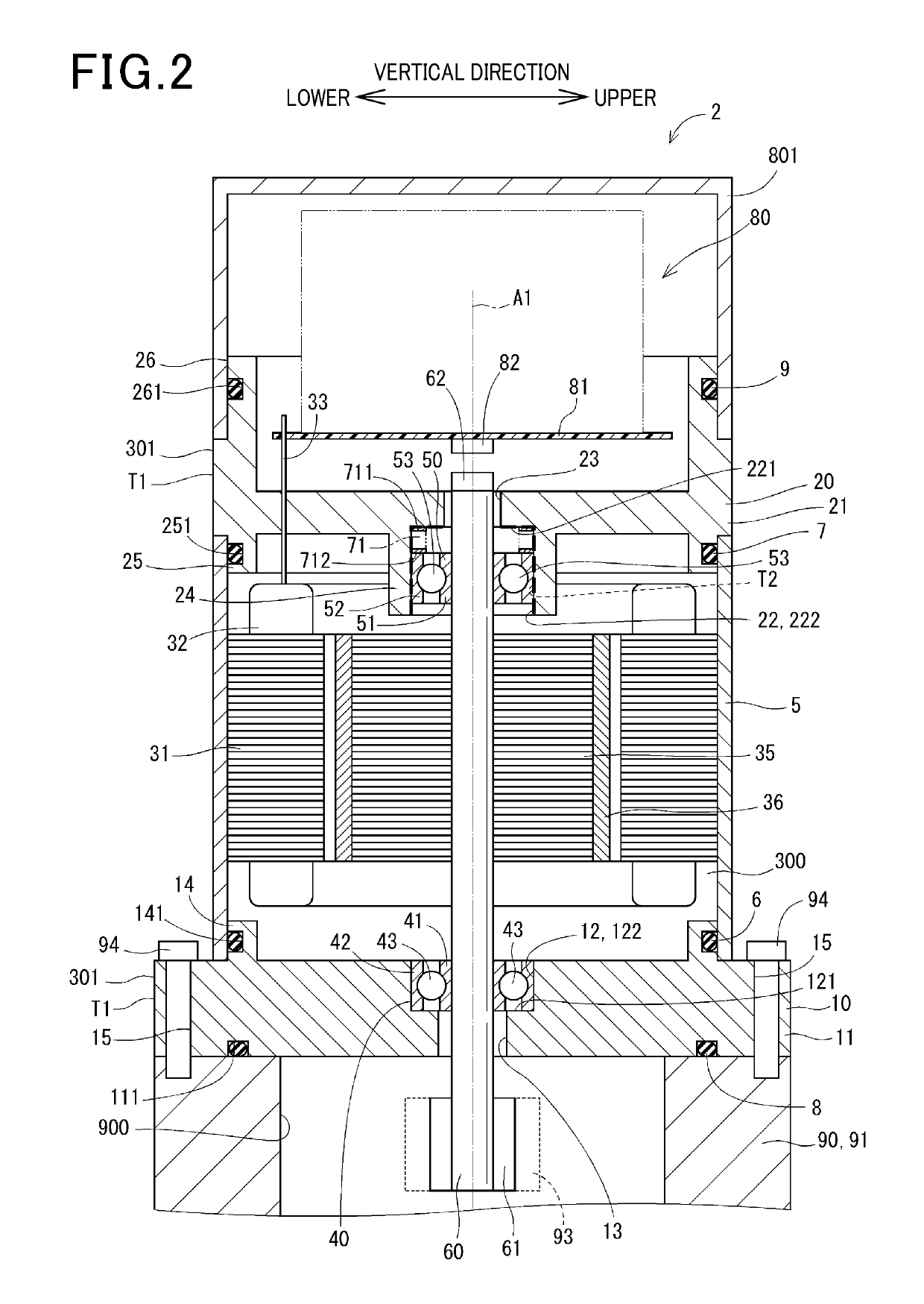
[0038]FIG. 2 illustrates the electric motor 2 according to the first embodiment. The electric motor 2 is supplied with electric power to produce torque and used in, for example, an electric power-steering device mounted in vehicles, such as automobiles, to assist a vehicle operator in turning the steering wheel.
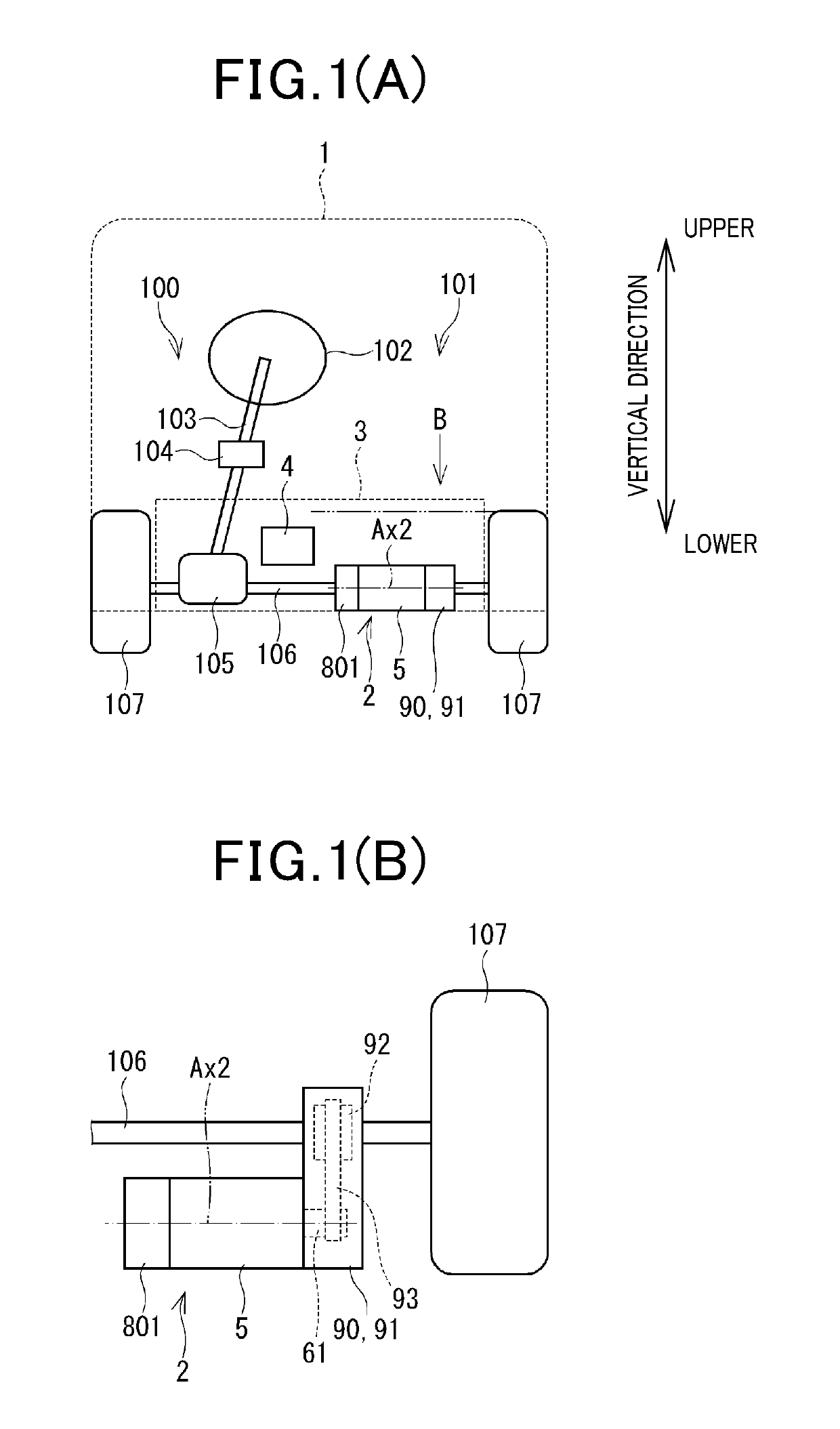
[0039]FIG. 1(A) illustrates an entire structure of the steering system 100 equipped with the electric power steering device 101. The electric power steering device 101 is equipped with the torque sensor 104 mounted on the steering shaft 103 connecting with the steering wheel 102. The torque sensor 104 works to measure a degree of steering torque exerted by an operator or a driver of the vehicle 1 on the steering shaft 103 through the steering wheel 102.
[0040]The steering shaft 103 has the pinion gear 105 mounted on an end thereof. The pinion gear 105 meshes with the rack shaft 106. The rack shaft 106 has a pair of wheels 107 secured to ends thereof through a tie rod to be rot...
third embodiment
[0134]FIG. 6 illustrates the electric motor 2 according to the third embodiment which is different in layout of the biasing member 71 from the first embodiment.
[0135]The first bearing 40 and the first bottom wall 121 define an annular chamber therebetween. The biasing member 71 is mounted in the annular chamber between the first bottom wall 121 and the first bearing 40 and exert spring load on the shaft 60 through the first bearing 40, thereby pressing the shaft 60 in the lengthwise direction toward the second bearing 50.
[0136]Specifically, the biasing member 71 is compressed in the axial direction thereof (i.e., the first bearing 40) and mounted between the first bottom wall 121 and the first bearing 40. The biasing member 71, as can be seen in FIG. 6, has the end 711 placed in contact with the first bottom wall 121 and the end 712 placed in contact with one of opposed ends of the first outer cylinder 42 which faces the first bottom wall 121, so that it biases the first outer cylin...
fifth embodiment
[0151]FIG. 8 illustrates the electric motor 2 according to the fifth embodiment which is equipped with the biasing member 73 different in structure from the biasing member 71 of the first embodiment.
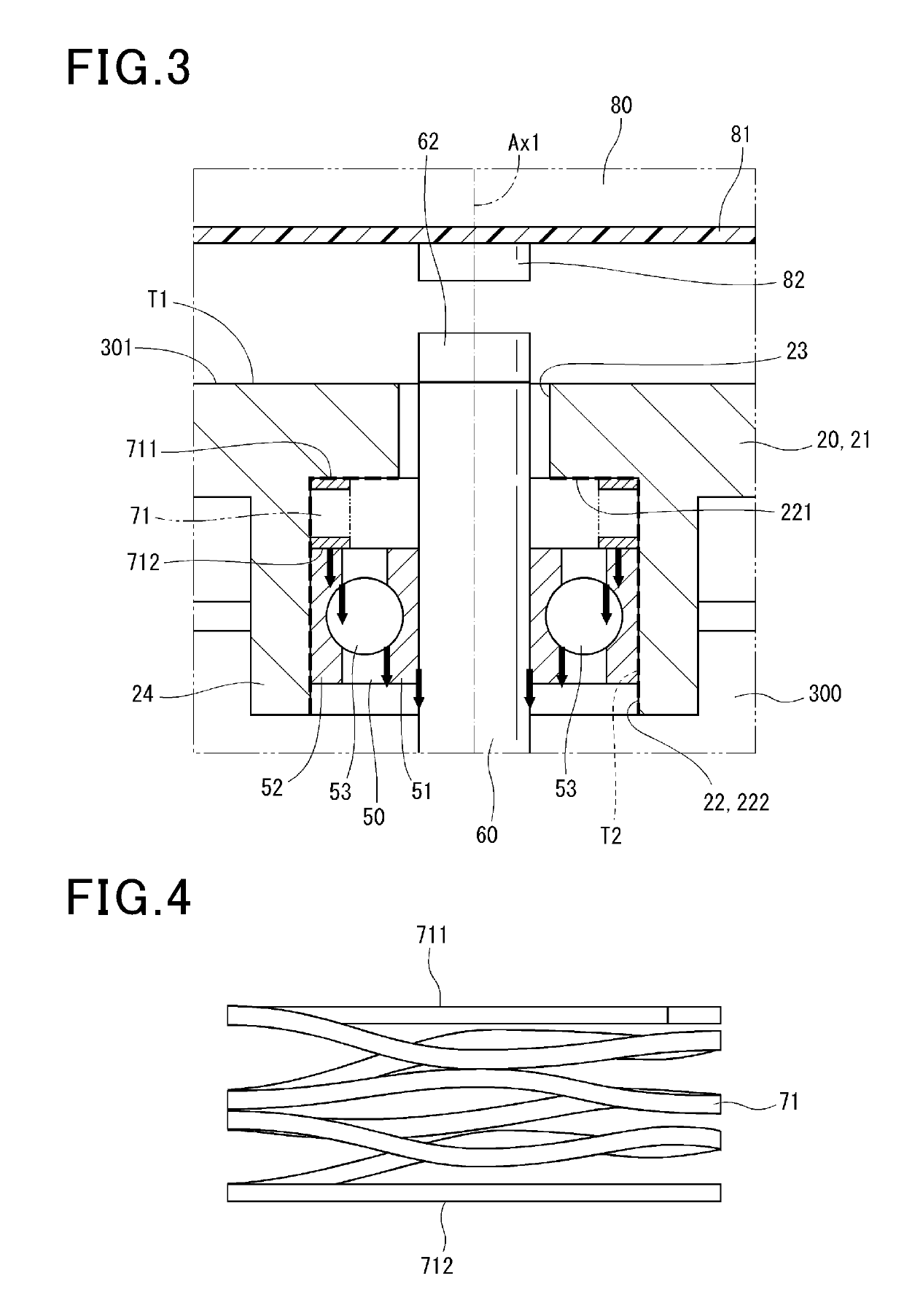
[0152]The biasing member 73 is disposed between the second bottom wall 221 and the second bearing 50.
[0153]The biasing member 73 works to elastically press the shaft 60 through the second bearing 50 in the axial direction thereof toward the first bearing 40.
[0154]The biasing member 73 is made of austenite stainless steel and implemented in this embodiment by a coil spring.
[0155]Specifically, the biasing member 73 is compressed in the axial direction thereof (i.e., the second bearing 50) and mounted in an annular chamber defined between the second bottom wall 221 and the second bearing 50. The biasing member 73, as can be seen in FIG. 8, has the end 731 placed in contact with the second bottom wall 221 and the end 732 placed in contact with one of opposed ends of the second outer cylinder...
PUM
 Abstract
Description
Claims
Application Information
 - R&D
- Intellectual Property
- Life Sciences
- Materials
- Tech Scout
- Unparalleled Data Quality
- Higher Quality Content
- 60% Fewer Hallucinations
Browse by: Latest US Patents, China's latest patents, Technical Efficacy Thesaurus, Application Domain, Technology Topic, Popular Technical Reports.
© 2025 PatSnap. All rights reserved.Legal|Privacy policy|Modern Slavery Act Transparency Statement|Sitemap|About US| Contact US: help@patsnap.com


