Magnet retaining arrangements

a technology of magnet retaining arrangement and magnetic material, which is applied in the direction of magnetic circuit rotating parts, dynamo-electric machines, and magnetic circuit shape/form/construction, etc., can solve the problems of brittle permanent magnet material from which the pole piece is formed, prone to fracture and corrosion, and achieve the effect of reducing eddy current losses

Active Publication Date: 2015-11-24
GE ENERGY POWER CONVERSION TECH
View PDF18 Cites 2 Cited by
  • Summary
  • Abstract
  • Description
  • Claims
  • Application Information

AI Technical Summary

Benefits of technology

[0006]The present invention provides an improved permanent magnet rotor arrangement for a rotating electrical machine which in a preferred arrangement attempts to significantly reduce eddy current losses. More particular, the permanent magnet rotor arrangement comprises a rotor body (or rotor drum), a circumferential array of magnet carriers spaced apart from the rotor body in the radial direction and secured to the rotor body for rotation therewith, each magnet carrier having a surface, and at least one pole piece made of permanent magnet material located adjacent to the surface of each magnet carrier.
[0008]The permanent magnet material from which the pole piece is formed can be brittle and prone to fracture and corrosion. This is particularly the case when the permanent magnet material is high-energy-product or rare earth magnet material. A pole piece wrapper or retainer can therefore be used to enclose the pole piece to provide environmental (and optionally also mechanical) protection for the permanent magnet material and contains the permanent magnet material in the event that the material forming the pole piece fractures or disintegrates. It also protects the permanent magnet material from external contaminants, thereby minimising the risk of corrosion.
[0011]The advantages of the rotor arrangement are simplicity of construction, the ability to pre-assemble complete pole arrangements and the ease with which the pole pieces may be removed and replaced if this is desirable.

Problems solved by technology

The permanent magnet material from which the pole piece is formed can be brittle and prone to fracture and corrosion.

Method used


Image

  • Magnet retaining arrangements
  • Magnet retaining arrangements
  • Magnet retaining arrangements

Examples


Embodiment Construction

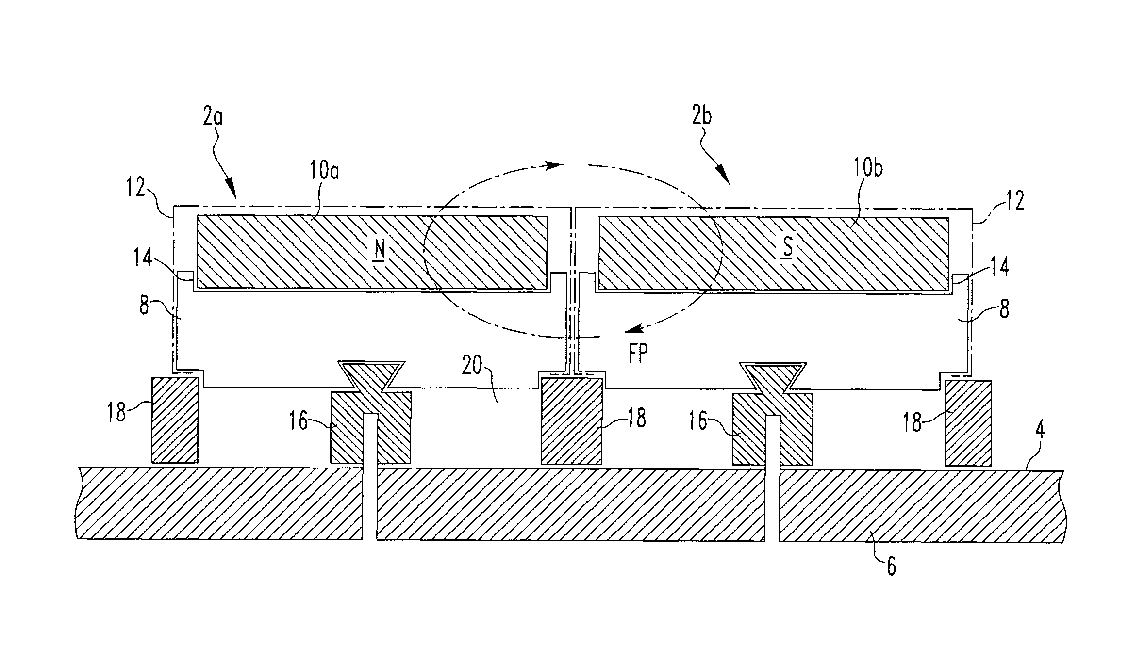
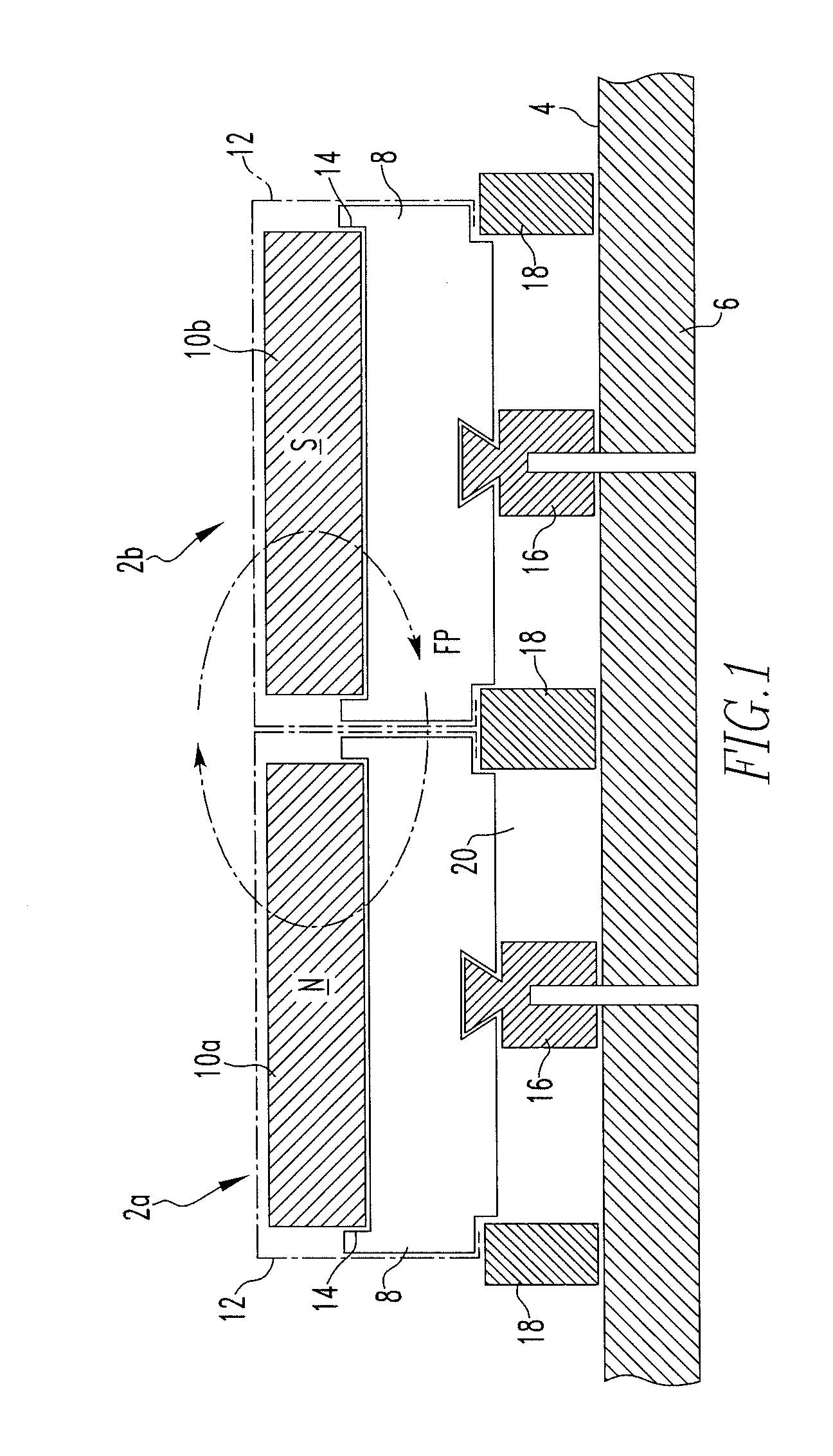
[0026]With reference to FIG. 1 a permanent magnet rotor arrangement for an electrical machine includes a circumferential array of magnet retaining assemblies 2 (only two of which are shown) that are secured around the radially outer surface 4 of a rotor drum 6. Each magnet retaining assembly 2 includes a laminated magnet carrier 8. The individual laminations are stamped out from magnetic lamination steel and assembled together to form the magnet carrier. A first magnet retaining assembly 2a includes a pole piece 10a that defines a North pole of the rotor. A second magnet retaining assembly 2b includes a pole piece 10b that defines a South pole of the rotor. The overall permanent magnet rotor arrangement is constructed so that circumferentially adjacent pole pieces define alternating North and South poles of the rotor. Although in the arrangement shown in FIG. 1 each magnet carrier 8 carries a single axially extending pole piece 10, it will be readily appreciated that each magnet car...


PUM


Abstract

The present invention provides a permanent magnet rotor arrangement for a rotating electrical machine including a rotor body having an outer rim. A circumferential array of magnet carriers is mounted to the rotor body by fixing members and support members and is spaced apart from the rotor body in the radial direction to define a series of axially gaps or spaces which can optionally be used as passages for cooling air. At least one pole piece made of permanent magnet material is located adjacent to a surface of each magnet carrier. The magnet carriers and pole pieces preferably have a laminated or divided construction to virtually eliminate eddy currents that may be particularly problematic in certain types and construction of electrical machine. The flux path between adjacent pole pieces flows in the circumferential direction within the magnet carriers and does not use the rotor body.

Description

CROSS REFERENCE TO RELATED APPLICATION[0001]This application claims priority to European Patent Application No. 11002715.8, filed Apr. 1, 2011.FIELD OF THE INVENTION[0002]The present invention relates to a magnet retaining arrangements, and in particular to arrangements for retaining permanent magnets on a rotor body of a rotating electrical machine such as a motor or generator.BACKGROUND TO THE INVENTION[0003]EP 1860755 discloses a permanent magnet rotor arrangement where a circumferential array of magnet carriers is affixed directly to the rim of a rotor body or drum. A pole piece made of permanent magnet material is located adjacent to a surface of each magnet carrier and in a channel formed in an associated inverted U-shaped pole piece retainer. The pole piece retainer is made of non-magnetic material.[0004]Such a rotor arrangement is particularly suitable for rotors in which the flux passes through the pole pieces predominantly in the radial direction and into the rim of the ro...

Claims


Application Information

Patent Timeline
Patent Type & Authority Patents(United States)
IPC IPC(8): H02K1/27H02K1/30H02K1/28H02K1/32
CPCH02K1/30H02K1/278H02K1/32
Inventor CLARK, PAUL EATON
Owner GE ENERGY POWER CONVERSION TECH
Why Eureka
Try Eureka