Optical component and method of making the same

a technology of optical components and components, applied in the field of optical components, can solve the problems of residual internal stress increased stress, and vacuum bubble generation in the optical component, and achieve the effect of small size and without increasing molding tim

Active Publication Date: 2016-03-15
CANON KK
View PDF15 Cites 2 Cited by
  • Summary
  • Abstract
  • Description
  • Claims
  • Application Information

AI Technical Summary

Benefits of technology

[0008]With the present invention, the outer shape of an optical component, which includes a core lens and a covering plastic that are integrated with each other, and the outer shape of the core lens can be made equivalent to each other. Therefore, a thick optical component having a smaller size can be obtained without increasing a molding time while preventing generation of a vacuum bubble (void) and a residual internal stress in the optical component.

Problems solved by technology

However, as the thickness of an optical component increases, an increase in stress occurs due to the difference between contraction of a surface plastic layer, which first solidifies during a molding process, and contraction of an inner plastic portion, which solidifies afterwards.
Therefore, problems in that a vacuum bubble (void) is generated in the optical component and a residual internal stress remains in the optical component occur.
There is another problem in that a considerably long cycle time is required to mold a thick optical component, because a considerably longer cooling time is required to cool a thicker optical component.
Therefore, the outer shape of the optical component becomes larger than that of the core lens, so that it is difficult to reduce the size of the optical component with this method.

Method used


Image

  • Optical component and method of making the same
  • Optical component and method of making the same
  • Optical component and method of making the same

Examples


first embodiment

[0024]FIGS. 1A to 3B illustrate an optical component according to a first embodiment of the present invention. The same parts will be denoted by the same numerals and redundant description will be omitted.

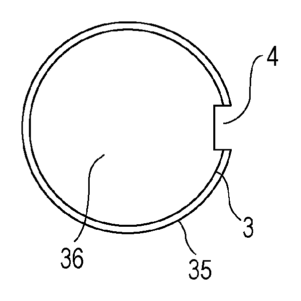
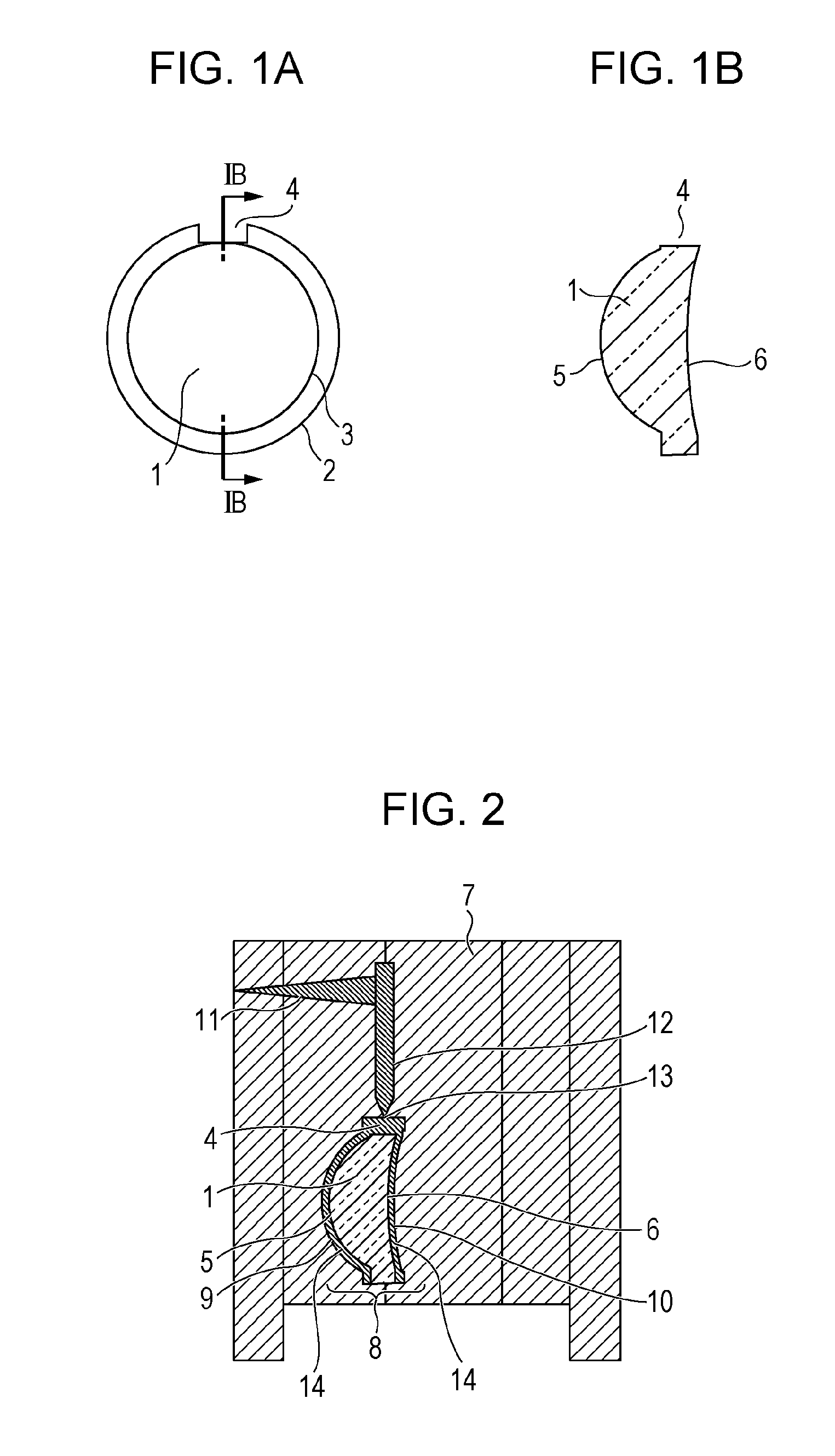
[0025]FIG. 1A is a plan view of a core lens 1 and FIG. 1B is a sectional view of the core lens 1 taken along line IB-IB of FIG. 1A. FIGS. 1A and 1B illustrate the core lens 1, an outer periphery 2 of the core lens 1, an optically effective area 3, a recessed portion 4, a front optical surface 5, and a back optical surface 6. In the present specification, the surfaces 5 and 6 will be referred to as the front and back surfaces 5 and 6 of the core lens 1. Which of the surfaces 5 and 6 is a front surface and which of these is a back surface are not particularly limited.

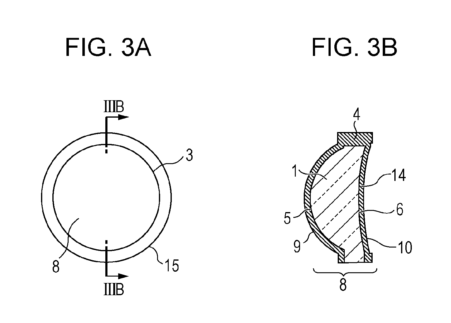
[0026]FIG. 2 is a sectional view of an example of a mold for molding an optical component according to the present invention. FIG. 2 illustrates an optical component injection mold 7, an optical component 8, a front opti...

second embodiment

[0031]FIGS. 7A to 8C illustrate an optical component according to a second embodiment of the present invention. The same parts as those of FIGS. 1A to 3B will be denoted by the same numerals and redundant description will be omitted. The shape of the surface of the recessed portion 4 according to the present embodiment in at least the optically effective area is characterized in that the shape continuously changes. Moreover, in the present embodiment, the shape of the surface of the recessed portion 4 in at least the optically effective area may be a shape such that dY / dX is continuous in at least the optically effective area, where X is the optical axis direction and Y is a direction perpendicular to the optical axis direction in a cross section parallel to the optical axis.

[0032]FIG. 7A is a perspective view of a core lens according to the present embodiment, FIG. 7B is a sectional view of the core lens taken along a plane VIIB that passes through the recessed portion 4 and that i...

example 1

[0054]An example 1 will be described.

[0055]First, a core lens injection mold was placed in an injection molding machine, and a melted plastic (cycloolefin) for forming a core lens was introduced into the mold through a sprue, a runner, and a gate. Subsequently, a core lens was obtained by performing a cooling process, a mold opening process, and an ejection process. The core lens was a meniscus lens having a central thickness of 6 mm and an oval shape with a height of 16 mm and a width of 18 mm. The core lens had an optically effective area having an oval shape with a height of 12 mm and a width of 14 mm therein. The recessed portion had a width of 4 mm and a depth of 2 mm. The recessed portion was formed along the draft, and a part of the recessed portion was disposed in the optically effective area.

[0056]Next, an optical component injection mold was placed in an injection molding machine. The core lens was inserted into the optical component injection mold by using a positioning m...


PUM

PropertyMeasurementUnit
angleaaaaaaaaaa
widthaaaaaaaaaa
heightaaaaaaaaaa

Abstract

A recessed portion, through which a covering plastic that has been melted and that is used for covering a core lens is introduced in a bifurcating manner, is formed in the core lens, and the covering plastic is introduced simultaneously onto the front and back surfaces of the core lens through the recessed portion.

Description

BACKGROUND OF THE INVENTION[0001]1. Field of the Invention[0002]The present invention relates to an optical component that is used for an optical apparatus such as a digital camera or a copier and a method of making the optical component.[0003]2. Description of the Related Art[0004]There's an increasing demand for making thick optical components by using an injection molding method in recent years. However, as the thickness of an optical component increases, an increase in stress occurs due to the difference between contraction of a surface plastic layer, which first solidifies during a molding process, and contraction of an inner plastic portion, which solidifies afterwards. Therefore, problems in that a vacuum bubble (void) is generated in the optical component and a residual internal stress remains in the optical component occur. There is another problem in that a considerably long cycle time is required to mold a thick optical component, because a considerably longer cooling tim...

Claims


Application Information

Patent Timeline
Patent Type & Authority Patents(United States)
IPC IPC(8): G02B27/10G02B3/00G02B11/00G02B13/00G02B15/00G02B17/00G02B25/00B29D11/00B29C45/14
CPCB29D11/0073B29C45/14065B29C45/14819G02B3/00B29C45/1679B29C45/0046B29C2045/1682B29D11/00009B29D11/00538
Inventor KIKUCHI, WATARUKOBAYASHI, DAIGO
Owner CANON KK
Why Eureka
Try Eureka