
Systems and methods for VSLAM optimization

a technology of optimization system and vslam, applied in the direction of vehicle position/course/altitude control, process and machine control, instruments, etc., can solve the problems of inability to use preexisting maps, laborious, and laborious, and achieve the effect of reducing labor intensity, reducing labor intensity, and reducing labor intensity

Active Publication Date: 2016-03-15
IROBOT CORP
View PDF110 Cites 34 Cited by
  • Summary
  • Abstract
  • Description
  • Claims
  • Application Information

AI Technical Summary

Benefits of technology

The patent describes a method for localization and mapping in a system using a processor and a camera. The method involves updating a graph with new edges and removing certain edges if they exceed certain thresholds. The method can also identify new landmarks and update the graph based on these landmarks. The technical effect of this patent is to improve the accuracy and efficiency of localization and mapping in systems using a processor and camera.

Problems solved by technology

Such “pure” localization systems are disadvantageous because generating a map via manual techniques is a relatively difficult, labor-intensive, and specialized task.
For example, the rearranging of furniture in a room can render a preexisting map unusable.
As a result, maps in pure localization systems are subject to relatively frequent and costly updates such that the map accurately represents its surroundings.
Such laser rangefinder techniques, while accurate, are relatively unreliable in dynamic environments such as environments where people are walking.
In addition, a laser rangefinder is a relatively expensive instrument, and can be cost prohibitive for many robot applications.
The cost of filter updates increases quadratically with the number of features tracked, and the tracking is not robust to discontinuous motion or low frame rates.

Method used


Image

  • Systems and methods for VSLAM optimization
  • Systems and methods for VSLAM optimization
  • Systems and methods for VSLAM optimization

Examples


Embodiment Construction

[0093]Although this invention will be described in terms of certain preferred embodiments, other embodiments that are apparent to those of ordinary skill in the art, including embodiments that do not provide all of the benefits and features set forth herein, are also within the scope of this invention.

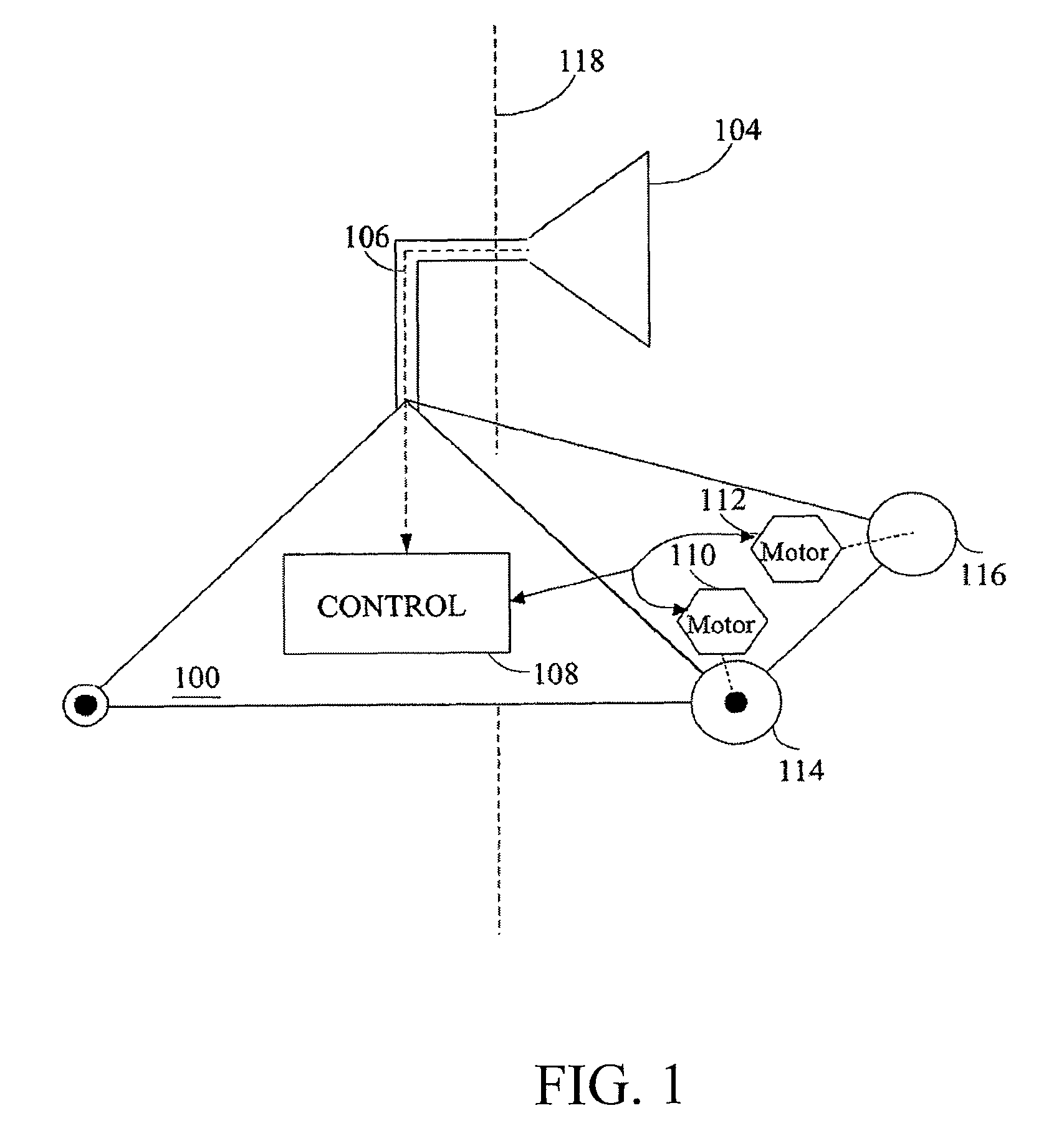
[0094]Embodiments of the invention advantageously use one or more visual sensors and one or more dead reckoning sensors to process Simultaneous Localization and Mapping (SLAM). The combination of SLAM with visual sensors will hereafter be referred to as VSLAM. Advantageously, such visual techniques can be used by a vehicle, such as a mobile robot, to autonomously generate and update a map. In one embodiment, VSLAM is advantageously used by a portion of a vehicle, such as by an “arm” of a vehicle. In contrast to localization and mapping techniques that use laser rangefinders or other range-based devices or sensors, the visual techniques are economically practical in a wide range of appl...


PUM


Abstract

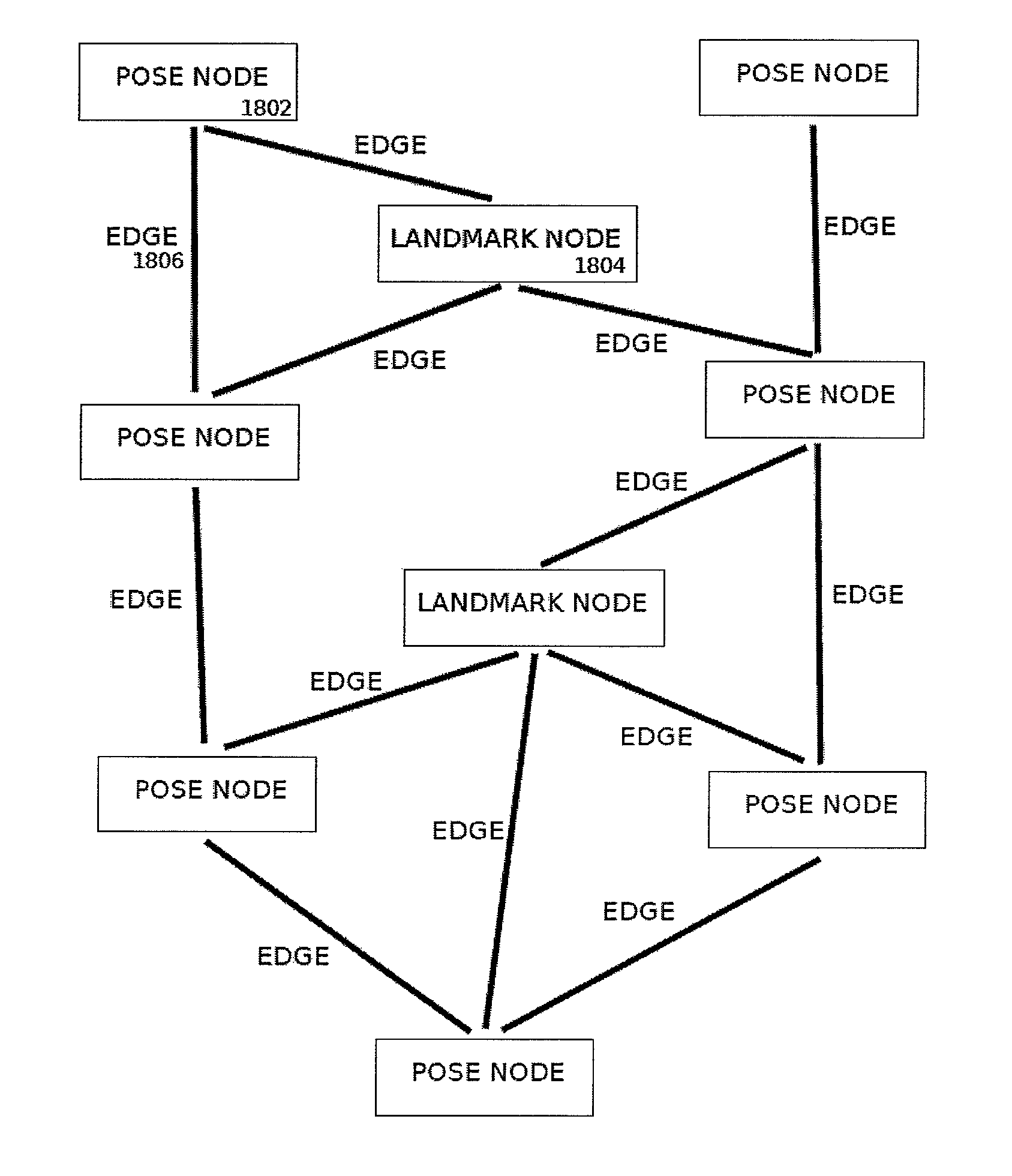
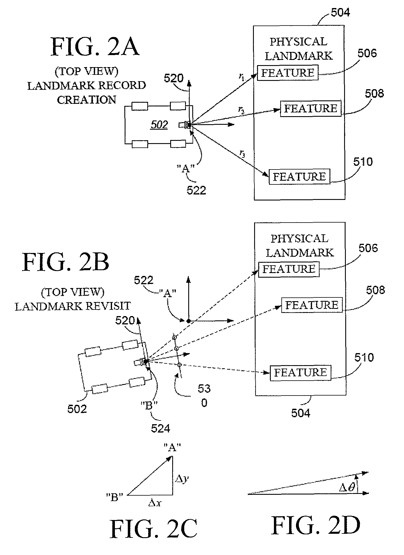
The invention is related to methods and apparatus that use a visual sensor and dead reckoning sensors to process Simultaneous Localization and Mapping (SLAM). These techniques can be used in robot navigation. Advantageously, such visual techniques can be used to autonomously generate and update a map. Unlike with laser rangefinders, the visual techniques are economically practical in a wide range of applications and can be used in relatively dynamic environments, such as environments in which people move. Certain embodiments contemplate improvements to the front-end processing in a SLAM-based system. Particularly, certain of these embodiments contemplate a novel landmark matching process. Certain of these embodiments also contemplate a novel landmark creation process. Certain embodiments contemplate improvements to the back-end processing in a SLAM-based system. Particularly, certain of these embodiments contemplate algorithms for modifying the SLAM graph in real-time to achieve a more efficient structure.

Description

CROSS-REFERENCE TO RELATED APPLICATIONS[0001]This application claims priority to Provisional Application 61 / 404,001 filed on Sep. 24, 2010, the disclosure of which is hereby incorporated by reference in its entirety herein. This application is further related to issued U.S. Pat. No. 7,774,158, filed Dec. 17, 2003 titled SYSTEMS AND METHODS FOR LANDMARK GENERATION FOR VISUAL SIMULTANEOUS LOCALIZATION AND MAPPING, the disclosure of which is hereby incorporated by reference in its entirety herein.TECHNICAL FIELD[0002]The invention generally relates to navigation of mobile electronic devices. In particular, the invention relates to front-end and back-end processing for localization and mapping techniques that can be used in mobile electronic systems, such as in mobile robots.BACKGROUND OF THE INVENTION[0003]Mobile robots are becoming more and more commonplace in society. It will be understood that these robots can be embodied in a variety of forms, such as in automated vacuum cleaners. ...

Claims


Application Information

Patent Timeline
Patent Type & Authority Patents(United States)
IPC IPC(8): G09B29/00
CPCG09B29/007G05D1/0274G05D1/0246G06F16/24G06F16/29G06F16/444G06F16/24578G05D1/0253G06F18/22
Inventor EADE, ETHANMUNICH, MARIO E.FONG, PHILIP
Owner IROBOT CORP
Learn More