Vacuum cleaner agitator cleaner with power control

a technology of agitator and vacuum cleaner, which is applied in the direction of vacuum cleaner apparatus, cleaning equipment, electric equipment installation, etc., can solve the problems of reducing the performance of the agitator in a variety of ways, collecting a significant amount of various kinds of dirt and debris on the agitator, and rotating the agitator used in vacuum cleaners

Active Publication Date: 2016-03-29
AB ELECTROLUX
View PDF161 Cites 15 Cited by
  • Summary
  • Abstract
  • Description
  • Claims
  • Application Information

AI Technical Summary

Problems solved by technology

It has been found that rotating agitators used in vacuum cleaners, floor sweepers, and the like, can collect a significant amount of various kinds of dirt and debris on the agitator itself.
It has also been found that accumulated debris can reduce the performance of the agitator in a variety of ways.
For example, debris may cover the agitation bristles and diminish the agitator's ability to agitate a surface.
Further, debris on the agitator may impede the rotation of the agitator by wrapping around the axle or by creating additional friction with the cleaning head.
If not removed, such debris can also accumulate on or migrate to the ends of the agitator and enter the bearing areas where it may cause binding, remove bearing lubrication, or otherwise generate high friction, excessive heat, or other undesirable conditions that can damage the bearings or mounting structure.
In addition, debris collected on the agitator may create an imbalance in the agitator that may result in sound and / or vibrations when the agitator rotates.
Debris that has collected on an agitator is often difficult to remove because it has wrapped tightly around the agitator and intertwined with the bristles.
Manual removal can be unsanitary, time consuming and, if the user fails to follow instructions to deactivate the vacuum, may expose the user to contact with a moving agitator.

Method used


Image

  • Vacuum cleaner agitator cleaner with power control
  • Vacuum cleaner agitator cleaner with power control
  • Vacuum cleaner agitator cleaner with power control

Examples


Embodiment Construction

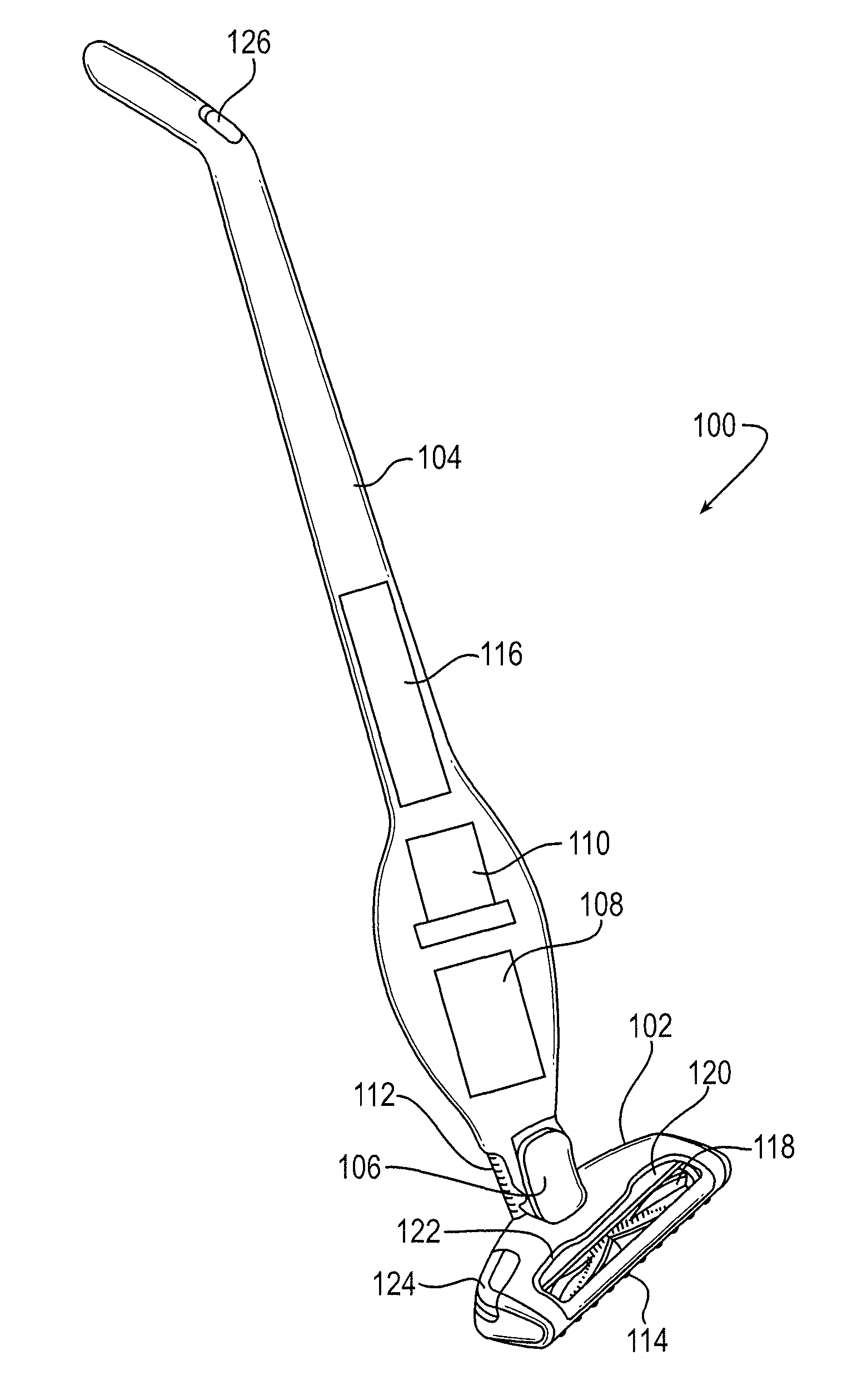
[0019]An exemplary embodiment of an upright vacuum cleaner 100 is shown in FIG. 1. In general, the vacuum cleaner 100 includes a base 102, a handle 104, and a pivot joint 106 connecting the base 102 to the handle 104.

[0020]The exemplary handle 104 includes a dirt collector 108, such as a bag chamber or cyclone separator, and a suction motor 110 (i.e., a combined impeller and electric motor) configured to suck air through the dirt collector 108. The handle 104 is connected to the base 102 by a suction hose 112, and the suction hose 112 is fluidly connected to a suction inlet 114 located on the bottom of the base 102. The vacuum cleaner 100 may be powered by a battery pack 116, a cord to a household power supply, a combination of the foregoing, or the like.

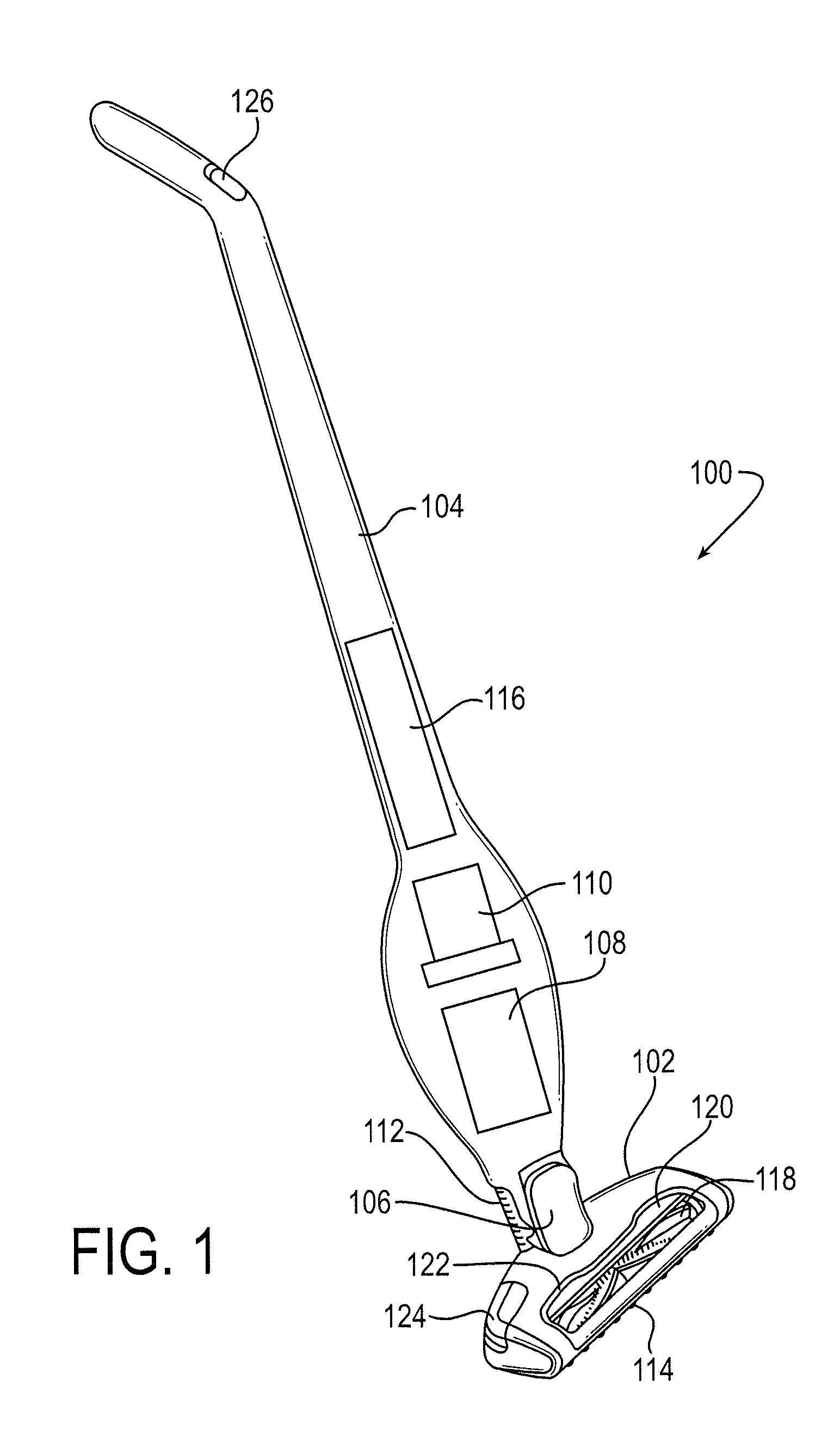
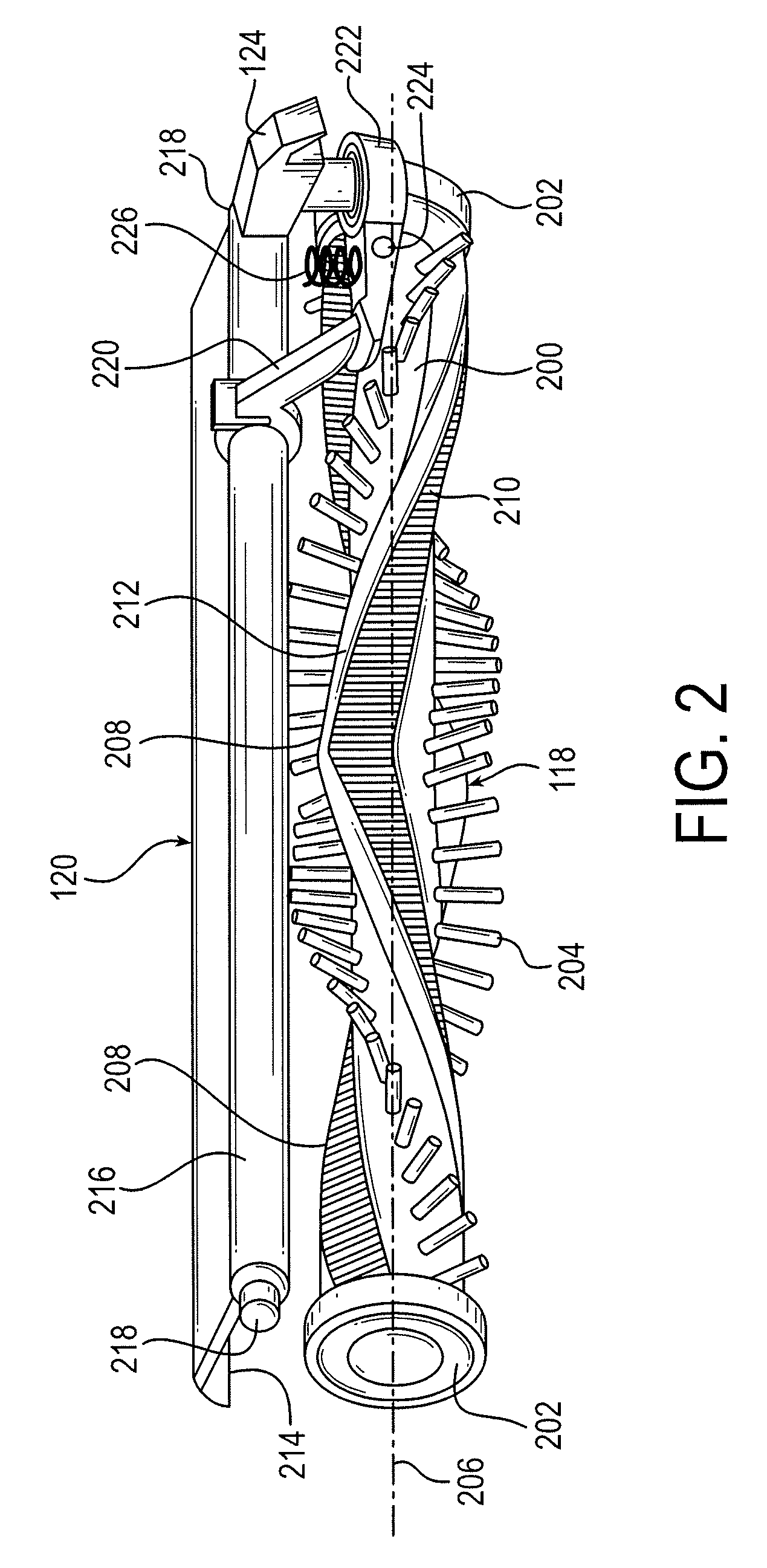
[0021]The exemplary base 102 includes a rotating floor agitator 118 and an agitator cleaner 120. These may be visible to the user through a window 122 on the surface of the base 102. A foot pedal 124 or other mechanism may be provid...


PUM


Abstract

A vacuum cleaner agitator system having an agitator, an electric motor to rotate the agitator, a power source, and an agitator cleaner. The cleaner moves between a first position in which it is spaced from the agitator and a second position in which it engages the agitator to remove debris while the agitator rotates. The system also has a detector configured to indicate when the cleaner is in the second position. A drive control system connects the electric motor, electric power source, and agitator cleaning detector. The drive control system has a first drive mode to drive the electric motor at a first power level, and a second drive mode, activated upon receiving an indication from the detector that the cleaner is in the second position, to drive the electric motor at a second power level that is greater than the first power level.

Description

BACKGROUND OF THE INVENTION[0001]1. Field of the Invention[0002]The present invention relates generally to cleaning devices and, more specifically, to cleaning device agitators having features for removing dirt and debris from the agitator.[0003]2. Description of the Related Art[0004]It is well known in the art of cleaning devices to use agitators to clean surfaces such as carpets, upholstery, and bare floors. These agitators can function in a variety of ways and appear in many forms. One typical embodiment of an agitator is a tube or shaft that rotates around its longitudinal axis and has one or more features that agitate the surface as it rotates. Such features typically include one or more bristle tufts, flexible flaps, bumps, and so on. These are commonly referred to as “brushrolls,” but other terms have been used to describe them. The agitator moves or dislodges dirt from the surface, making it easier to collect by the cleaning device. Agitators are useful in a variety of clean...

Claims


Application Information

Patent Timeline
Patent Type & Authority Patents(United States)
IPC IPC(8): A47L9/04A47L9/28A46B13/00
CPCA47L9/0477A47L9/0411A47L9/2805A47L9/2842A47L9/2857A47L9/2894A46B13/006A47L9/2889Y02B40/82Y02B40/00
Inventor ERIKSSON, HENRIK
Owner AB ELECTROLUX
Why Eureka
Try Eureka