
Vacuum cooler

a cooler and vacuum technology, applied in the field of vacuum coolers, can solve the problems of prolonging the effectiveness of the cooler, addressing no efficient way of reducing the effect of radiant, convective or conducive heat, and removing the decomposition effect of oxygen from the product storage area

Active Publication Date: 2016-03-29
H E B LP
View PDF23 Cites 21 Cited by
  • Summary
  • Abstract
  • Description
  • Claims
  • Application Information

AI Technical Summary

Benefits of technology

The invention is a container for holding beverages, food, and other items that require refrigeration or heating without a power source for an extended period of time. The container is designed to keep the contents' ambient temperature maintained for longer periods of time by minimizing conductive, convective, and radiant heat while also removing the detrimental effects of oxygen. The container includes a vacuum sealed container and a radiant heat barrier to keep the stored products' ambient temperature maintained for longer periods of time. The invention improves upon previous coolers and cooling methods by keeping the stored products' ambient temperature and maximizing freshness.

Problems solved by technology

Though each of the aforementioned patents provides a solution to the expressed problem of preventing melted ice from coming into contact with the contents of the cooler, it in no way prolongs the effectiveness of a cooler by keeping the contents' ambient temperature maintained for longer periods of time.
The above patents address no efficient way of reducing the effects of radiant, convective or conducive heat, nor do they remove the decomposition effects of oxygen from the product storage area.
While this design does a good job at reducing radiant heat, the described air barrier between the inner and outer shell is far less efficient at reducing conductive and convective heat than removing air molecules all together.

Method used


Image

  • Vacuum cooler
  • Vacuum cooler
  • Vacuum cooler

Examples


Embodiment Construction

[0050]Various embodiments of the invention are described by reference to the drawings in which like numerals are employed to designate like parts. Various items of equipment that could be additionally employed to enhance functionality and performance such as fittings, mountings, sensors (e.g. temperature gages), etc., have been omitted to simplify the description. However, such conventional equipment and its applications are known to those of skill in the art, and such equipment can be employed as desired. Moreover, although the invention is described below in the context of the transport and storage of products that are sensitive to heat transfer and degradation due to oxygen present atmosphere, those skilled in the art will recognize that the invention has applicability to the transport and / or storage of many different refrigerated or frozen products or items, e.g. medical supplies, biological material, chemicals, and the like.

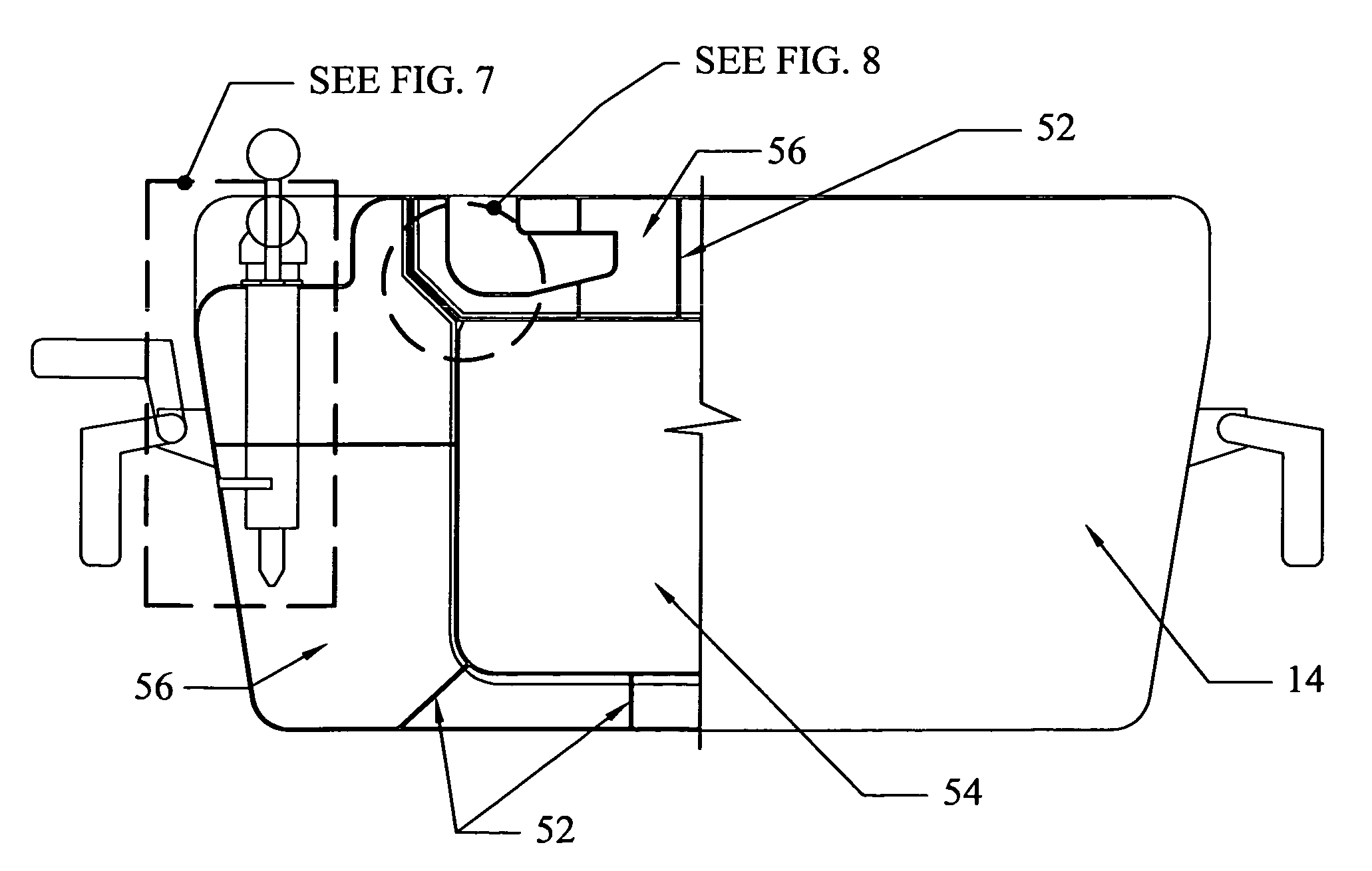
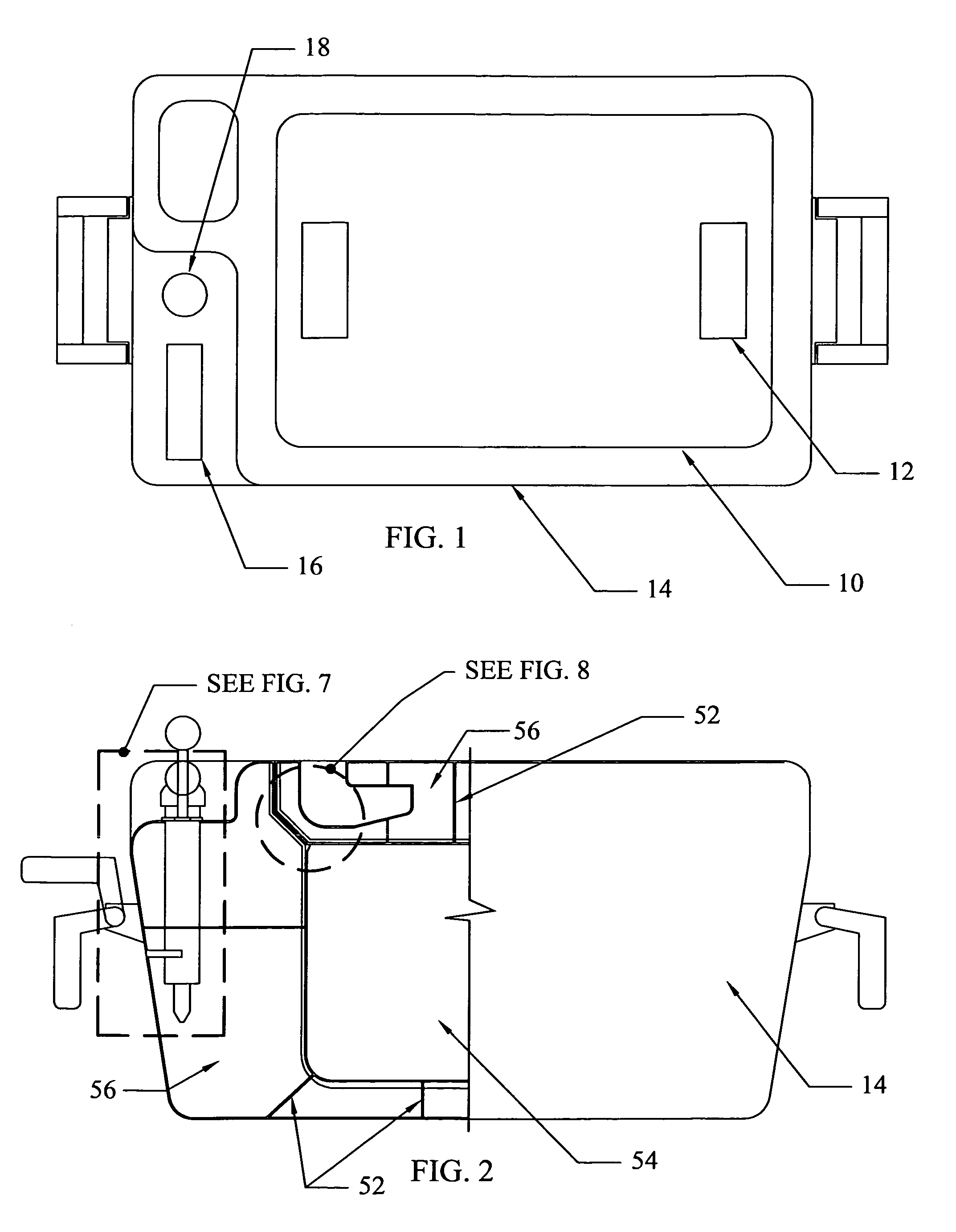
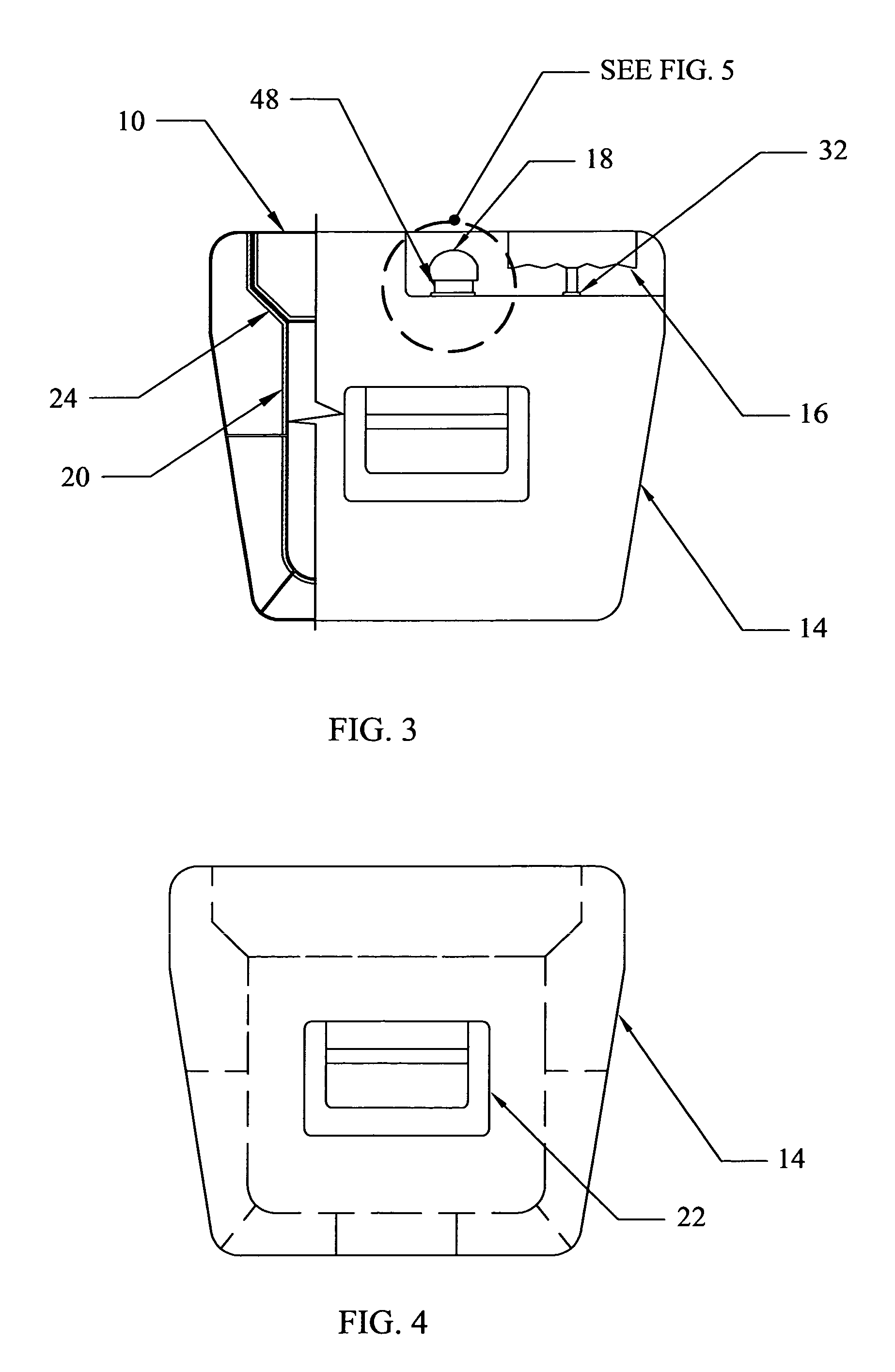
[0051]FIGS. 1 and 2 describe one embodiment of the coo...


PUM


Abstract

A portable, durable, lightweight cooler system designed to maintain beverages, food, medical supplies, drugs, and other heat sensitive products at existing temperatures with substantially reduced heat gain or loss from the surrounding environment for extended periods of time, when no power source is available. This container is designed to greatly reduce radiant heat transfer along with conductive and convective heat transfer while diminishing decomposition effects of stored items and thus maintaining freshness. This system includes a cooler housing, a reinforced lid, a radiation reflective material application, and a system to remove air from the containment area, thus creating a vacuum within the cooler itself and sealing the lid to the cooler housing. Upon actuation of a vacuum release device, air is reintroduced into the containment area thus allowing the lid to be removed and the stored products be accessed.

Description

BACKGROUND OF THE INVENTION[0001]1. Field of Invention[0002]This invention relates to an improved container for holding beverages, food, and other items that require lengthy storage time with reduced heat gain or loss while maintaining freshness when no power source is available for refrigeration or heating.[0003]2. Description of the Prior Art[0004]Beverages, food, medical supplies, drugs and other heat sensitive products requiring storage without a power source have generally been stored in insulated coolers or ice chests for a very limited time period. Although these coolers or chests have certainly evolved over the years, For instance, U.S. Pat. No. 5,671,611 to Quigley dated Sep. 30, 1997, U.S. Pat. No. 5,568,735 to Newkirk dated Oct. 29, 1996, and U.S. Pat. No. 4,872,589 to Englehart dated Oct. 10, 1989. These all address the issue of preventing melted ice from coming into contact with the contents of the cooler allowing the contents to become soggy. Though each of the aforeme...

Claims


Application Information

Patent Timeline
IPC IPC(8): B65D81/38B65B31/04
CPCB65D81/3818B65B31/04B65B31/00F25D3/08A45C11/20B65D81/2038B65D81/30B65D81/3813
Inventor WOOLDRIDGE, ERIC, NEWLANDJACOBS, DANIEL, BAILEY
Owner H E B LP
Learn More