Magnus rotor with balancing weights and method for balancing a body of revolution

a rotor and revolution technology, applied in the field of magnus rotors, can solve the problems of increasing the wear or even destruction of the bearings, reducing the stability of the rotor, and reducing the efficiency of the rotor, so as to achieve the effect of reducing the weight of the body

Active Publication Date: 2016-03-29
WOBBEN PROPERTIES GMBH
View PDF18 Cites 3 Cited by
  • Summary
  • Abstract
  • Description
  • Claims
  • Application Information

AI Technical Summary

Benefits of technology

[0011]Mounting the weights at such a predetermined location serves to balance the rotary body. In that respect, in the case of a rotary body in which it is no longer possible to assume that it behaves like a rigid body, such as for example a Magnus rotor, at least two planes are necessary in the axial direction of the axis of rotation to counteract deformation caused by imbalance.
[0017]In a preferred embodiment the openings are closed by cover members. The cover members can be fitted for example by way of a screw connection and can thus also be removed when required. That has the advantage that, in operation of the Magnus rotor, there is no safety risk for example for service personnel through the openings, but nonetheless access from the carrier is possible to the stiffening means if required for fitting balancing weights.
[0026]Preferably the balancing weights can be mounted to the stiffening means through openings in the carrier or can be removed from the stiffening means through the openings. Preferably the carrier is accessible and supports the rotary body. Preferably the openings are disposed on such a carrier. That guarantees easy accessibility to the locations at which the balancing weights have to be fitted and / or removed. In addition fitment or removal is possible at any location at which there is an opening. For removal purposes the weight bodies can be reduced by drilling, grinding or milling. Alternatively, in the case of a releasable connection such as for example a connection involving a threaded pin, the weight bodies can be dismantled.
[0030]In a further preferred embodiment, for n flexural eigenmode forms, m balancing weights are fitted in o axially mutually spaced planes arranged perpendicularly to the axis of rotation of the rotary body. In that case n, m and o are whole numbers of greater than 1. Additional balancing of the rigid rotary body can be advantageous. In that case balancing is effected in two further such planes. Thus, for n flexural eigenmode forms, m+2 balancing weights are fitted in o+2 planes. It is advantageous in that respect if, with additional balancing of the rigid rotary body, smooth running of the drive device is also achieved even at low rotary speeds. Thus for example when ten flexural eigenmode forms occur it would be possible to use ten or twelve balancing weights, while when for example three flexural eigenmode forms occur, it would be possible to use three or five balancing weights.
[0031]Preferably a Magnus rotor has one or more of the features which was or were described hereinbefore in connection with the description of the method. Such balancing on a Magnus rotor results in very precise balancing—fine balancing—in spite of the size and weight of the Magnus rotor, as for example the theoretically ascertained number of balancing planes is available and fitment and / or removal of the balancing weights at the required positions is easy to perform.

Problems solved by technology

Upon a rotary movement of the Magnus rotor, particularly in the case of large Magnus rotors, imbalances can occur due to asymmetrical distribution of mass.
By virtue of the imbalances, oscillations occur which disturb smooth running of the Magnus rotor and can lead to increased wear of the bearings or even destruction thereof.
If however a sailing rotor is so long in the axial direction that no longer behaves a rigid body, simple balancing is no longer sufficient to achieve stable rotary movement without imbalance.

Method used


Image

  • Magnus rotor with balancing weights and method for balancing a body of revolution
  • Magnus rotor with balancing weights and method for balancing a body of revolution
  • Magnus rotor with balancing weights and method for balancing a body of revolution

Examples


Embodiment Construction

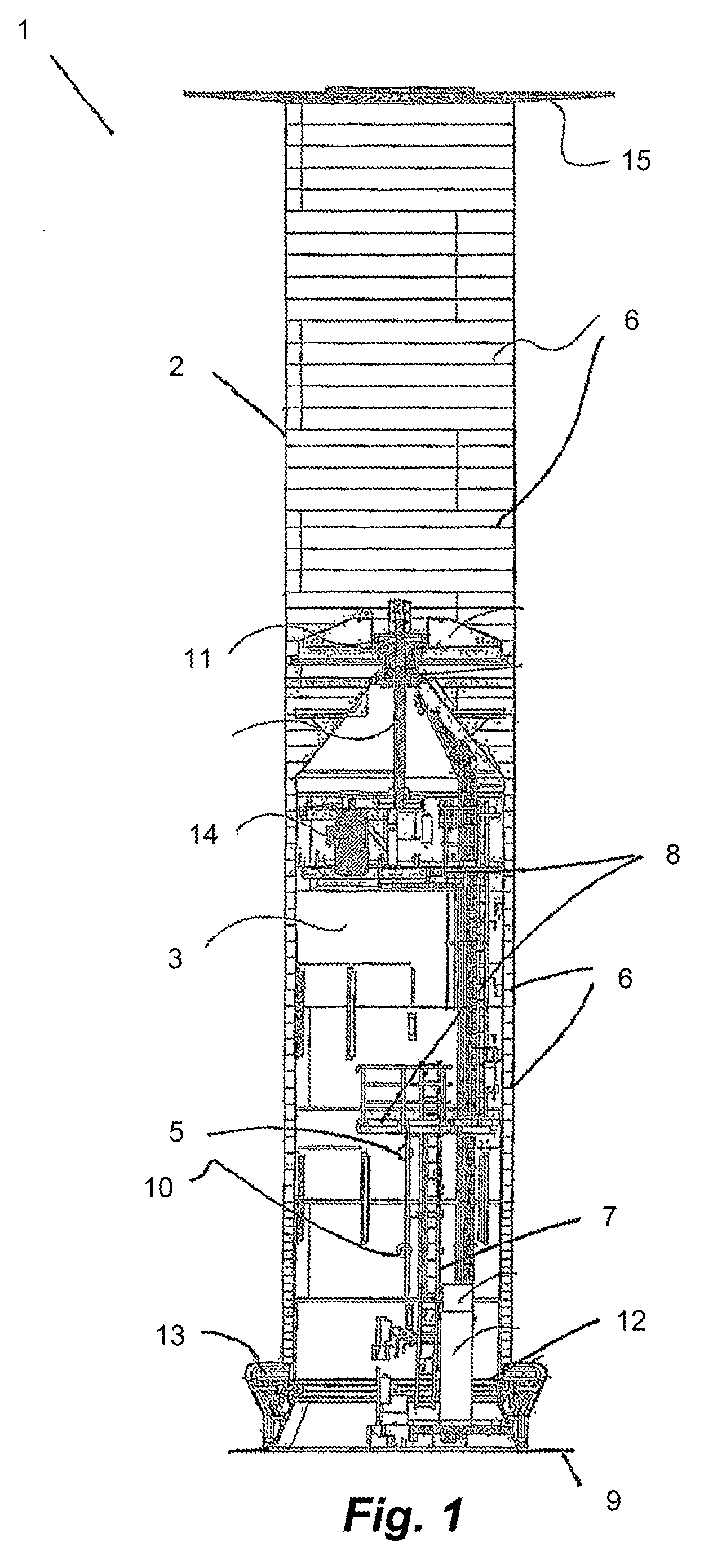
[0040]Referring to FIG. 1 the Magnus rotor 1 includes a rotary body 2 which is adapted to rotate and which is rotationally symmetrical relative to an axis of rotation and which is supported by way of a carrier 3. The rotary body 2 is a cylindrical hollow body which stands perpendicularly on a plane 9 which is part of a ship—hereinafter referred to as the ship's plane. Shown on the inside of the rotary body 2 are ribs 6 serving as stiffening means for stiffening the rotary body 2. They extend in the peripheral direction of the rotary body 2. In addition the ribs 6 are used for receiving balancing weights. For that purpose the ribs are provided with recesses, holes and / or projections at regular spacings in the peripheral direction. It is possible to use screwthreaded pins for connecting the balancing weights to the ribs 6. The ribs 6 extend over the entire periphery in the axial direction with respect to the axis of rotation at a predetermined spacing relative to each other. In that c...


PUM

PropertyMeasurementUnit
heightaaaaaaaaaa
angleaaaaaaaaaa
angleaaaaaaaaaa

Abstract

The invention relates to a Magnus rotor having a cylindrical body of revolution for converting wind power into a feed force using the Magnus effect. The Magnus rotor having: a rotational shaft about which the body of revolution rotates; a support member on which the body of revolution is mounted; and a body of revolution which has stiffening ribs for the reinforcement thereof. The body of revolution is primed in at least two planes arranged at a mutual spacing in the axial direction perpendicular to the rotational shaft of the body of revolution in order to accommodate balancing weights. The invention further relates to a method for balancing a body of revolution according to the invention.

Description

BACKGROUND[0001]1. Technical Field[0002]The present invention concerns a Magnus rotor having a rotary body for converting the wind power into a propulsion power utilizing the Magnus effect and a method of balancing such a rotary body.[0003]2. Description of the Related Art[0004]A Magnus rotor, also referred to as a Flettner or sailing rotor or a similar rotationally symmetrical rotary body rotates about an axis of rotation and thereby, utilizing the Magnus effect, converts an air flow, in particular wind, into a force approximately transverse relative to the air flow, which can be used as a propulsion force.[0005]Upon a rotary movement of the Magnus rotor, particularly in the case of large Magnus rotors, imbalances can occur due to asymmetrical distribution of mass. By virtue of the imbalances, oscillations occur which disturb smooth running of the Magnus rotor and can lead to increased wear of the bearings or even destruction thereof.[0006]In the case of a rigid rotary body, in par...

Claims


Application Information

Patent Timeline
Patent Type & Authority Patents(United States)
IPC IPC(8): B63H9/02F03D7/02F03D3/00F03D1/00F03D3/06
CPCB63H9/02F03D1/008F03D3/067F03D7/0296F03D3/005Y02T70/58Y10T29/49316F03D13/35Y02E10/74B63B2035/009Y02T70/5236
Inventor ROHDEN, ROLFBOHLEN, THOMAS
Owner WOBBEN PROPERTIES GMBH
Why Eureka
Try Eureka