Aircraft capable of takeoff/landing via the fuselage thereof, and takeoff/landing system for the aircraft

a technology of fuselage and aircraft, which is applied in the direction of launching/towing gear, energy-saving operational measures, and alighting gear, etc., can solve the problems of limited weight of landing apparatus, limited weight of aircraft, and limited space available for landing, so as to reduce the weight of aircraft, reduce fuel consumption, and increase the effect of effective space within the aircra

Active Publication Date: 2016-04-05
DONGGYU YANG
View PDF18 Cites 7 Cited by
  • Summary
  • Abstract
  • Description
  • Claims
  • Application Information

AI Technical Summary

Benefits of technology

[0011]An object of the present disclosure is to provide a fuselage takeoff and landing enabled aircraft and a takeoff and landing system thereof in which a landing apparatus is removed and thus an aircraft body is taken off and landed in the state of being directly brought into contact with a virtual runway surface, thereby reducing the weight of an aircraft to enhance economic effects in the aviation field as well as reducing the number of aircraft takeoff and landing accidents.
[0031]Furthermore, the roller for takeoff and landing may be provided to increase or decrease the rotation speed while being synchronized in interlock with the driving speed of the aircraft fuselage.
[0036]According to a fuselage takeoff and landing enable aircraft and a takeoff and landing system thereof in accordance with the present disclosure, the existing heavy landing apparatus may be removed to allow the aircraft fuselage to be directly placed on a runway, thereby reducing the weight of the aircraft as much as the landing apparatus and the other members associated with the landing apparatus. Through this, fuel consumption can be reduced during the flight of the aircraft, and an effective space within the aircraft may be increased by removing or reducing a space required for the installation of the landing apparatus as well as reducing fuel capacity, thereby enhancing economic effects in the aviation industry.
[0037]Furthermore, it may be possible to reduce a thrust that should be generated by the aircraft due to using the power of a takeoff and landing apparatus in addition to a thrust of the engine generated by the relevant aircraft during the takeoff of the aircraft. Moreover, takeoff may be performed using the thrust of the aircraft and the power of the takeoff and landing apparatus at the same time or landing may be performed using a frictional force of the takeoff and landing apparatus to reduce the length of the runway, thereby further enhancing economic effects in the aviation industry.
[0038]In addition, a landing apparatus may be removed or the aircraft fuselage may be directly placed on a runway to perform takeoff and landing, and thus the aircraft can perform takeoff and landing in a safe manner, thereby greatly reducing aircraft accidents.

Problems solved by technology

However, in spite of the technological development, aircraft takeoff and landing accidents have been continued and gradually increased in their size and scope, but schemes for reducing the occurrence of takeoff and landing accidents and reducing the weight of aircraft through a change of aviation mechanism have been scarcely provided until the present.
However, if the weight of the landing apparatus is increased, then that of the aircraft will be also increased to that extent, and thus the weight of the landing apparatus will be limited to reduce the weight of the aircraft.
Furthermore, a conventional aircraft takes off using only a thrust of the engine generated by the relevant aircraft, and thus a lot of fuel is consumed during takeoff.

Method used


Image

  • Aircraft capable of takeoff/landing via the fuselage thereof, and takeoff/landing system for the aircraft
  • Aircraft capable of takeoff/landing via the fuselage thereof, and takeoff/landing system for the aircraft
  • Aircraft capable of takeoff/landing via the fuselage thereof, and takeoff/landing system for the aircraft

Examples


Embodiment Construction

[0060]Hereinafter, a fuselage takeoff and landing enabled aircraft and a takeoff and landing system thereof according to the present disclosure will be described in detail according to an embodiment illustrated in the accompanying drawings.

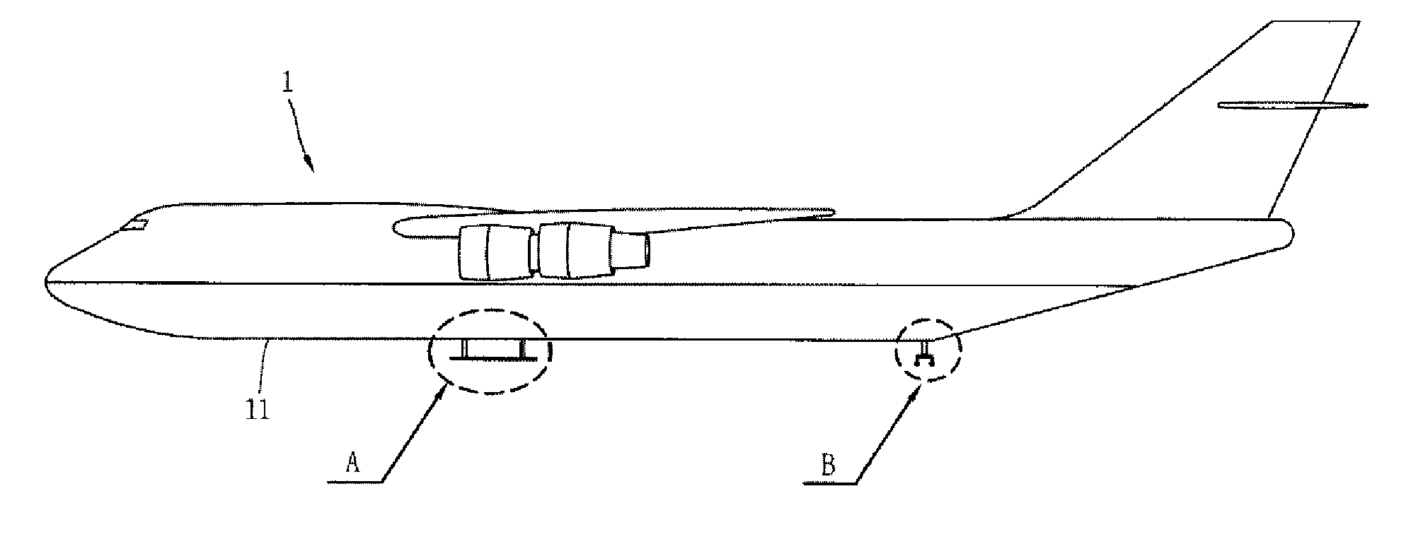
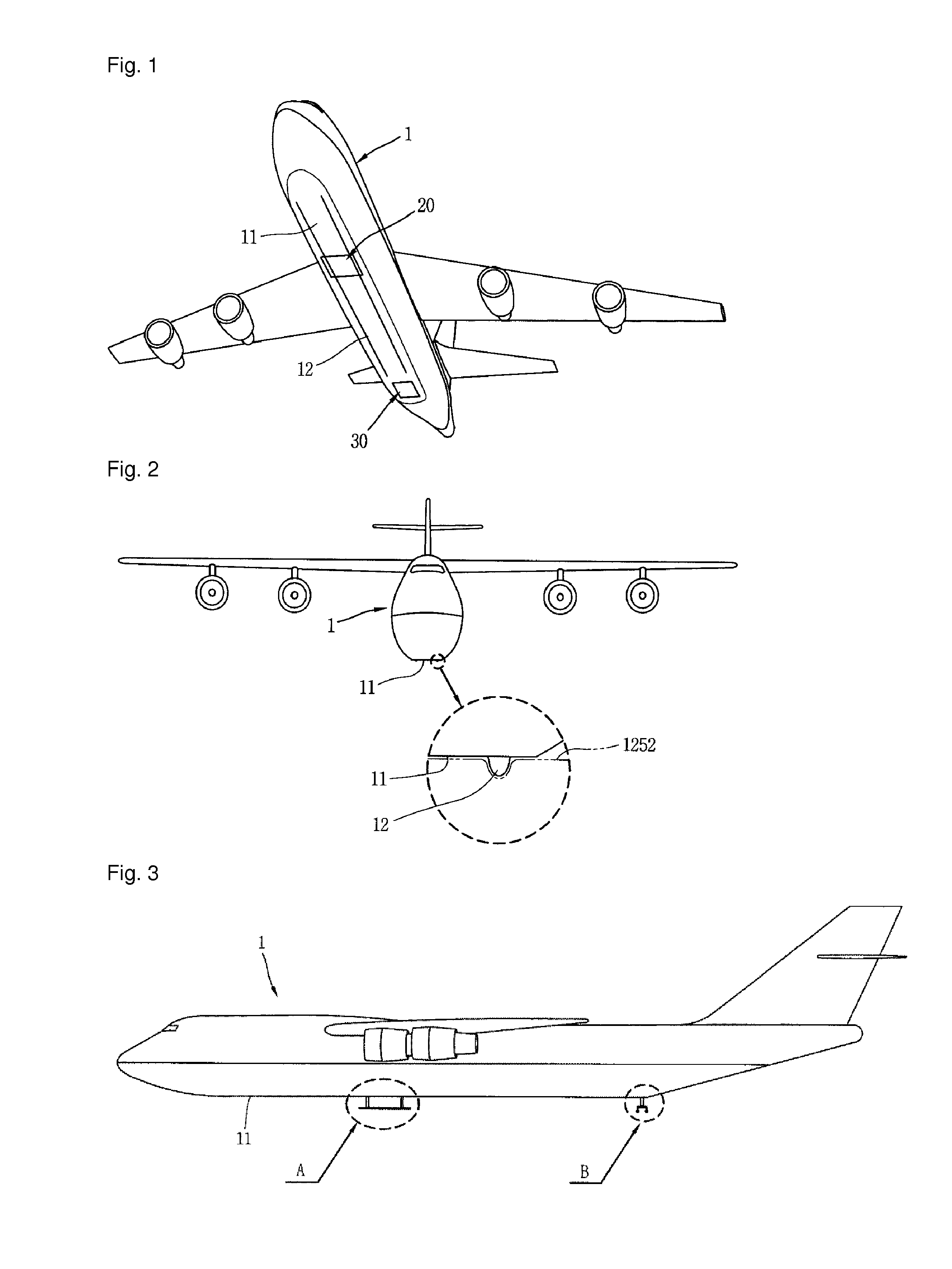
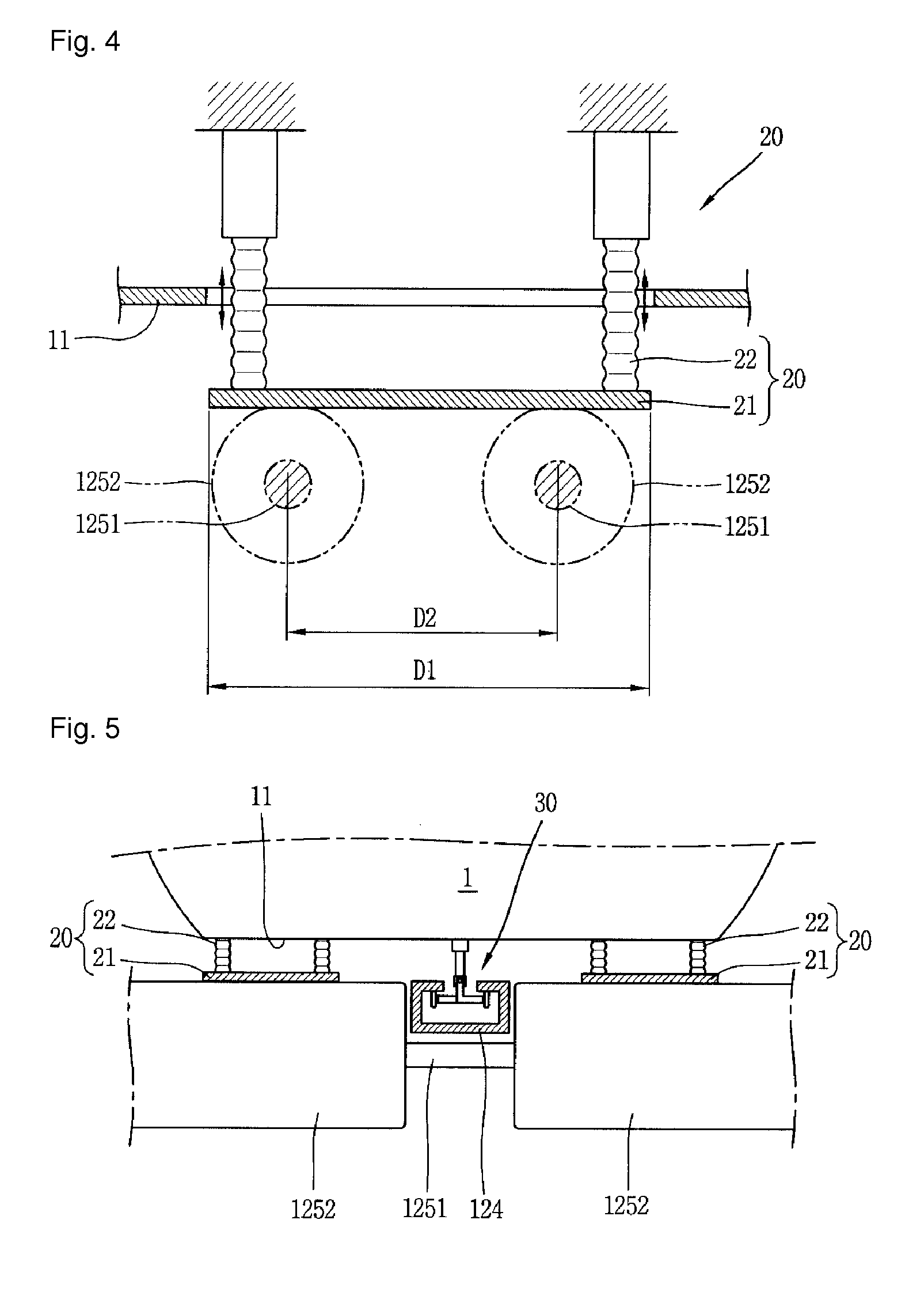
[0061]FIG. 1 is a bottom perspective view illustrating an aircraft capable of performing takeoff and landing according to the present disclosure, and FIG. 2 is a front view illustrating an aircraft according to FIG. 1.

[0062]As illustrated in FIGS. 1 through 3, an aircraft according to the present embodiment may be formed with a landing surface 11 having a plane at a bottom surface of the aircraft fuselage 1 such that a bottom surface of the aircraft fuselage 1 is directly placed on a virtual runway surface to perform takeoff and landing.

[0063]A typical aircraft is installed with a main landing gear at the main wing and a front landing gear (or nose landing gear) at a front side of the aircraft fuselage, respectively, but according to the present e...


PUM


Abstract

The aircraft capable of takeoff / landing via the fuselage thereof and the takeoff / landing system of the aircraft according to the present invention are configured such that multiple takeoff / landing rollers are arranged in a sliding direction such that the aircraft fuselage having a landing surface formed at the bottom thereof can safely land and slide in a sliding direction, thus enabling the aircraft fuselage to contact a running surface and takeoff / land without separate landing gear. Thus, not only can the weight of the aircraft be reduced, but the fuel consumption of the aircraft can be reduced as well, the useful space in the aircraft can be broadened, the length of the runway can be shortened due to the frictional force generated by the takeoff / landing device, and the safety during the takeoff / landing of the aircraft can be improved.

Description

CROSS-REFERENCE TO RELATED APPLICATIONS[0001]This application is a 371 U.S. National Stage of International Application No. PCT / KR2012 / 005698, filed on Jul. 17, 2012 and published in Korean as WO 2014 / 014136 A1 on Jan. 23, 2014. The entire disclosure of the above application is incorporated herein by reference.BACKGROUND OF THE INVENTION[0002]1. Field of the Invention[0003]The present disclosure relates to a fuselage takeoff and landing enabled aircraft without having a landing apparatus such as a landing gear, and a takeoff and landing system thereof.[0004]2. Description of the Related Art[0005]In general, the technologies of aircraft takeoff and landing having a fixed lift generation apparatus have been progressed in a state that takeoff and landing by means of a landing apparatus and takeoff and landing on a paved runway are regarded as the standard method since its initial powered flight. Accordingly, studies on the development of wing shapes, engine technologies, thermal resist...

Claims


Application Information

Patent Timeline
Patent Type & Authority Patents(United States)
IPC IPC(8): B64C25/32B64F1/02B64C25/04B64F1/04B64C25/62B64C25/14
CPCB64C25/32B64C25/04B64C25/14B64C25/62B64F1/02B64F1/04Y02T50/82Y02T50/80
Inventor YANG, DONGGYU
Owner DONGGYU YANG
Why Eureka
Try Eureka