Air brake service tool

Inactive Publication Date: 2016-04-12
ADAMS PERRY
View PDF15 Cites 3 Cited by
  • Summary
  • Abstract
  • Description
  • Claims
  • Application Information

AI Technical Summary

Benefits of technology

The patent describes a tool designed to service an air brake. The tool includes a sliding bar clamp with a movable jaw that can be locked in place. The tool also has a tube attached to the movable jaw that engages an anchor bolt on the air brake and a hook member attached to the other end of the bar to engage a push rod of the air brake. This tool makes it safe to remove a band clamp and access and replace the diaphragm of the air brake. It also allows for easy realignment of the housing parts and refastening of the band clamp.

Problems solved by technology

This tool, while useful in repairing drum brakes, is not particularly helpful in servicing air brake chambers.
A rear brake chamber is similar, but can be more complicated, because it often has two chambers, one for the service brake and another for an emergency or parking brake.

Method used


Image

  • Air brake service tool
  • Air brake service tool
  • Air brake service tool

Examples


Embodiment Construction

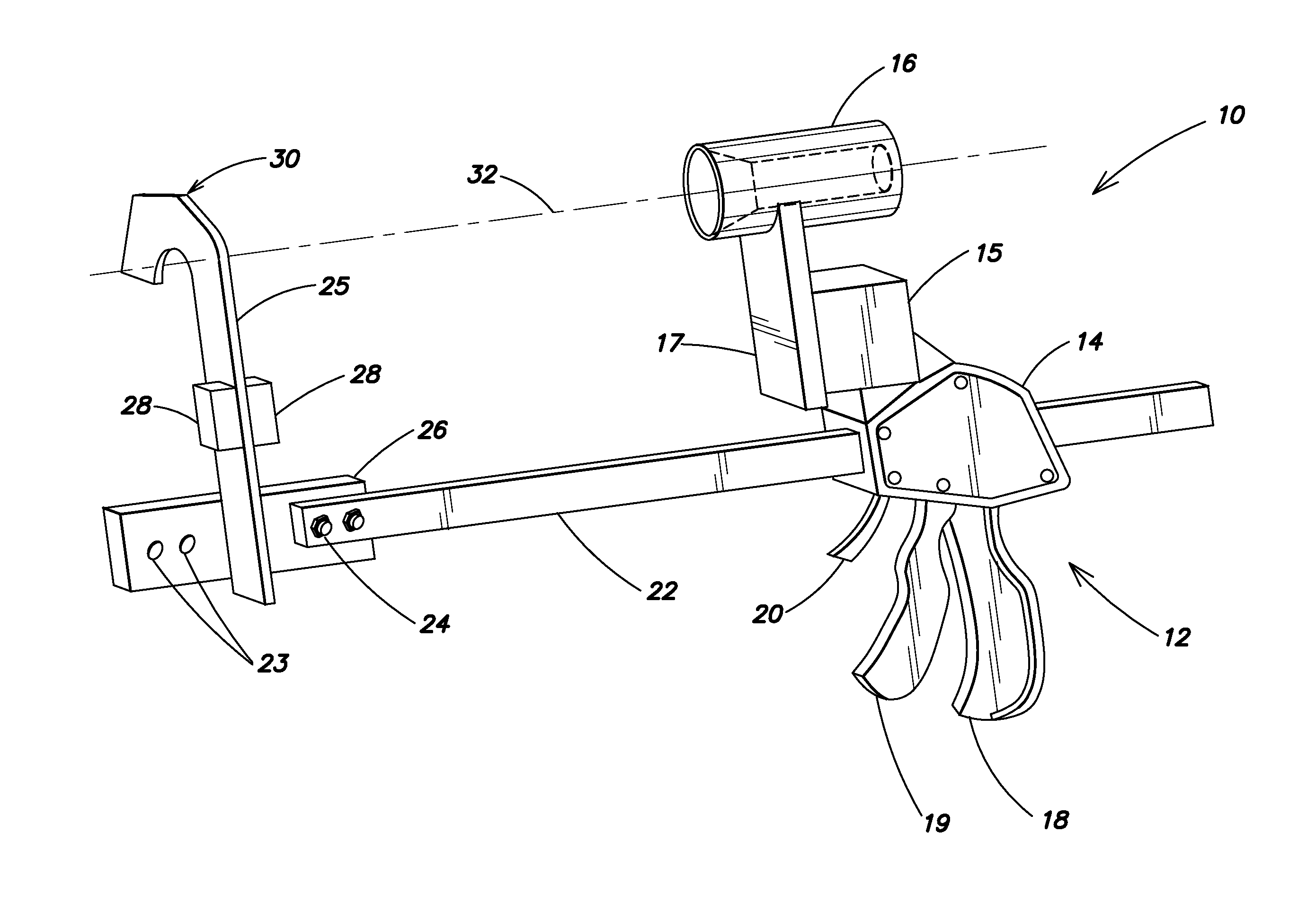
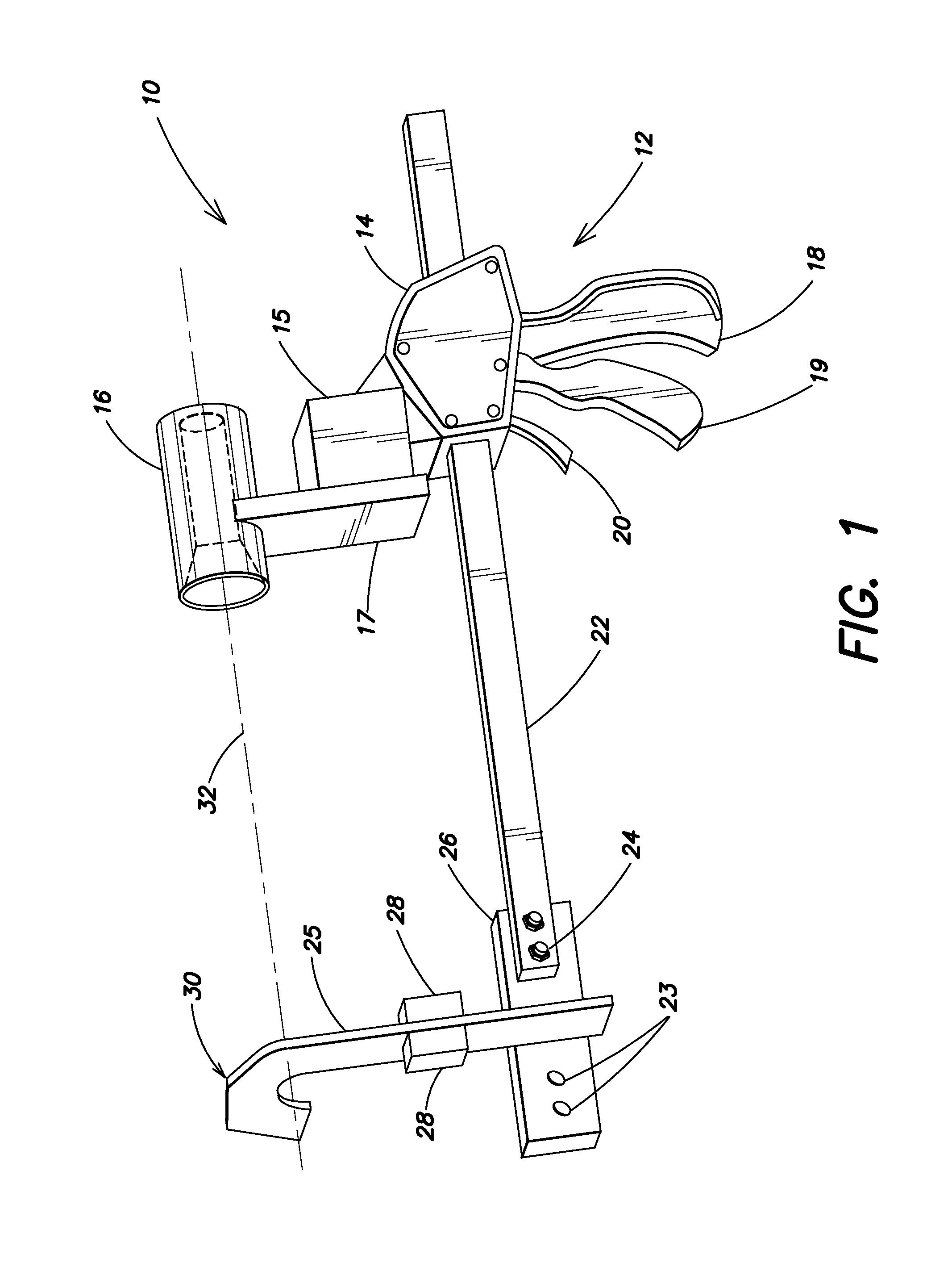
[0024]FIG. 1 shows a perspective view of an air brake service tool. The tool is used to disassemble and then reassemble an air brake chamber while the air brake remains on the vehicle. The tool is especially adapted for orderly removal of a band clamp, housing disassembly, swapping out the pancake diaphragm, reassembly of the housing, and reattachment of the band clamp. The tool avoids the need to support an inboard end of the air brake camber with a second pair of hands or a jack or some other arrangement.

[0025]More particularly, the tool 10 consists of a Quick-Grip® style clamp mechanism 12, including a head (or jaw) 14, handle 18, trigger 19, and release 20. Utilizing handle 18 and release 20 the head 14 is freed to slide back and forth along a bar 22. Head 14 includes a structure 17 serving to support a tubular head 16.

[0026]On the end of arm 22 opposite tubular head 16 is a reversible anchor hook assembly 30. Hook assembly 30 consists of hook portion 25 and base portion 26. Bas...


PUM


Abstract

A tool for servicing air brake systems. The tool includes a sliding bar locking mechanism. On one end of the bar is a movable, lockable tubular member; on the other end is a fixed hook member. The tool permits one person working alone to quickly replace an air brake diaphragm.

Description

BACKGROUND OF THE INVENTION[0001]1. Field of the Invention[0002]This patent application relates to air brakes and more particularly to a tool for holding air brake components in position on a vehicle during maintenance procedures.[0003]2. Background Information[0004]Air brake systems such as those used on semi-trailer trucks typically include one or more air brake assemblies at each wheel. Certain tools are already known for assembling or servicing brake chambers. U.S. Pat. No. 4,776,079 describes a clamping tool for supporting a handbrake while slowly releasing it against the action of a compression spring. This tool serves to securely hold together the brake can and brake drum during repair procedures. The tool includes a pair of handles that pivot with respect to one another and a pair of clamping arms carried by the handle members. One of the clamping arms includes an adjustable support leg.[0005]U.S. Pat. No. 6,009,608 describes a device for reassembling a brake system. The dev...

Claims


Application Information

Patent Timeline
IPC IPC(8): B25B11/00B25B27/30B25B27/00B25B5/16B25B5/02B25B7/02
CPCB25B27/304B25B5/02B25B5/163B25B27/0035B25B7/02B25B5/068
Inventor ADAMS, PERRY
Owner ADAMS PERRY
Why Eureka
Try Eureka