Nanocarbon generation equipment

Inactive Publication Date: 2008-10-23
KK TOSHIBA
View PDF7 Cites 2 Cited by
  • Summary
  • Abstract
  • Description
  • Claims
  • Application Information

AI Technical Summary

Benefits of technology

[0008]An object of the present invention is to provide a nanocarbon generation equipment which makes it possible to perform the removal of carbon product within shorter time and more safely as compared with the conventional equipment, and to easily perform the introduction of a catalyst into the equipment and the continuous removal of carbon product from the equipment even if the process is increased in scale, thus realizing mass production of nanocarbon.

Problems solved by technology

However, this conventional technique to treat organic processed materials is accompanied with various problems as explained below.
Namely, since this conventional technique is a batch treatment using a high-temperature furnace, it takes a lot of time before carbon can be taken out of the furnace after a series of processes including a step of loading the furnace with a catalyst and, after finishing the reaction, a step of cooling the interior of furnace.
Further, if carbon is taken out of the furnace when the temperature of carbon is still heated to a high temperature, there is a risk of burning of carbon.
Furthermore, since the reaction is performed in a reducing atmosphere, it may become difficult to maintain the reducing atmosphere if the process is to be performed on a large scale.
Additionally there is a problem that if the process is to be performed on a large scale, the introduction of a catalyst as well as the continuous removal of carbon product may become difficult.

Method used


Image

  • Nanocarbon generation equipment
  • Nanocarbon generation equipment
  • Nanocarbon generation equipment

Examples


specific embodiments

[0026]Next, specific embodiments of the nanocarbon generation equipment according to the present invention will be explained with reference to drawings.

first embodiment

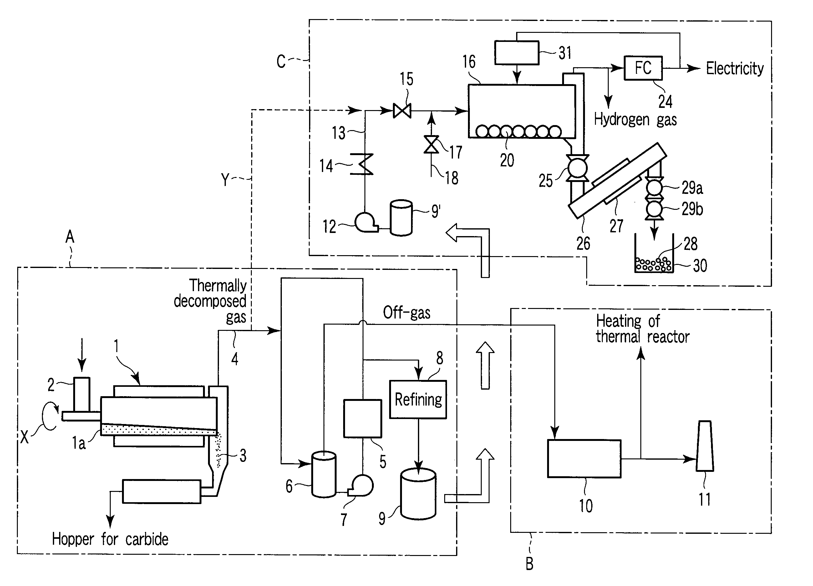
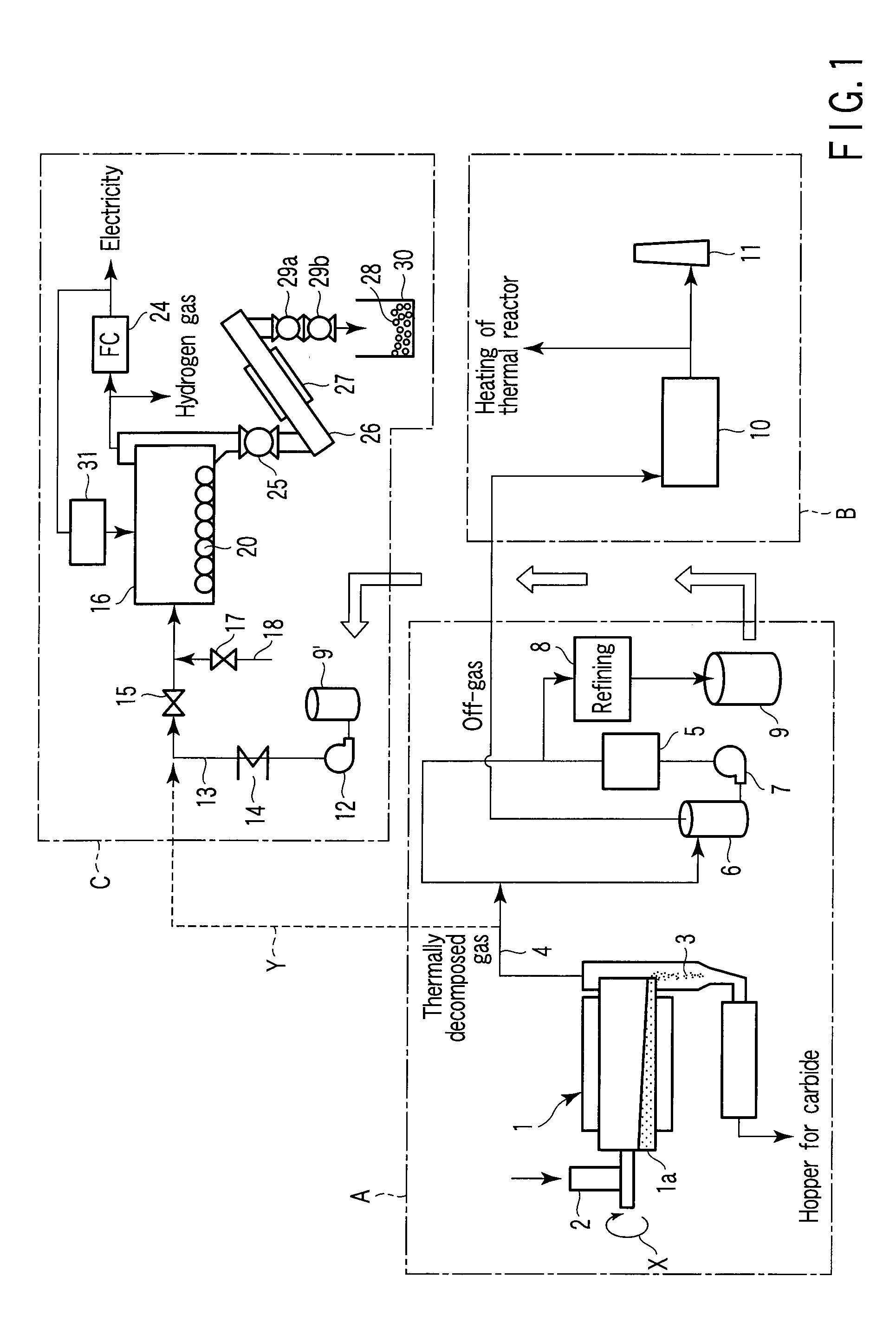
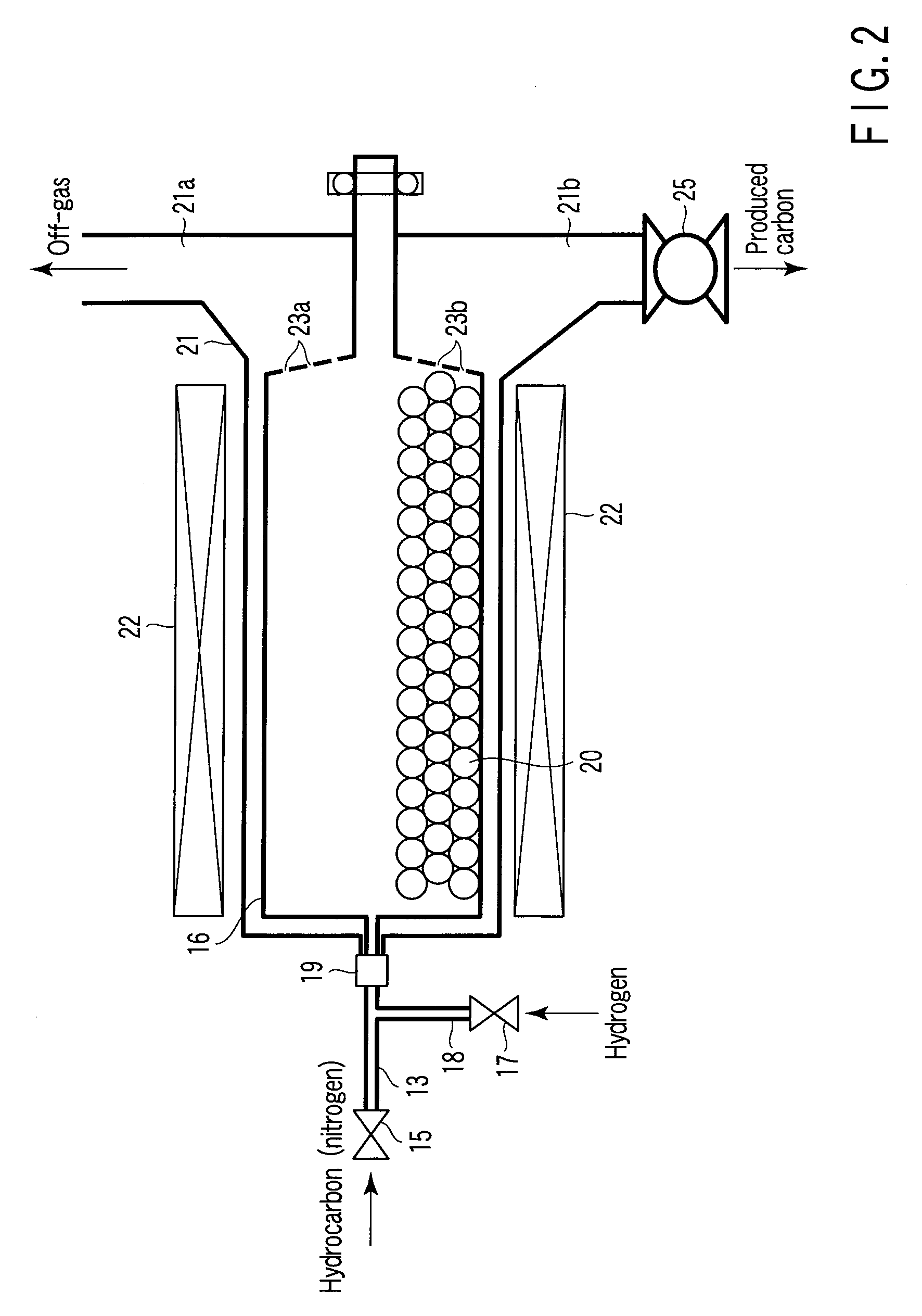
[0027]Referring to FIGS. 1 and 2, FIG. 1 is a process flowchart of the nanocarbon generation equipment according to a first embodiment of the present invention, and FIG. 2 is an enlarged diagram illustrating the rotary furnace and the peripheral structure thereof, both representing one constituent feature of the nanocarbon generation equipment of FIG. 1. This process flowchart is consisted of a block “A” illustrating a process including a step of loading a thermal reactor with a raw material, a step of recovering a liquefied matter and a step of refining the liquefied matter to obtain off-gas; a block “B” illustrating a process including a step of combusting the off-gas that has been obtained in the block “A” and a step of exhausting the combusted gas; and a block “C” illustrating a process including a step of heating and vaporizing bio-oil and a step of refining nanocarbon.

[0028]The reference number “1” in the drawing represents a thermal reactor wherein a raw material which has be...

second embodiment

[0045]Referring to FIG. 3, it illustrates only the rotary furnace of the nanocarbon generation equipment according to a second embodiment and the peripheral structure thereof. In this embodiment, the same members or portions as those of FIGS. 1 and 2 will be identified by the same reference numbers, thereby omitting the explanation thereof.

[0046]This embodiment is featured in that the rotary furnace 16 is loaded therein with a large number of super hard balls 41 made of toughened ceramics in addition to the metal balls 20 made of SUS, these super hard balls 41 being mixed with the metal balls 20.

[0047]According to this second embodiment, the surface of metal balls 20 is always scraped by the super hard balls 41, so that the surface of metal balls 20 can be activated, thus making it possible to peel off the carbon that has been deposited on the surface of metal balls 20. It should be noted that, since the inner wall of the rotary furnace 16 may be scraped by the super hard balls 41, ...


PUM

PropertyMeasurementUnit
Fractionaaaaaaaaaa
Concentrationaaaaaaaaaa
Densityaaaaaaaaaa

Abstract

A nanocarbon generation equipment designed such that organic processed materials can be quickly thermally decomposed therein and the decomposed materials are then quenched and liquefied to obtain liquefied materials is disclosed. This equipment comprises thermal reactor for quickly thermally decomposing the organic processed materials, apparatus for recovering the liquefied materials which are liquefied through quenching of thermally decomposed organic processed materials, a rotary furnace to be filled with a reducing atmosphere and loaded with hydrocarbons to be obtained through vaporization of liquefied materials after impurities contained in the liquefied materials are removed, and metal balls made of a metal selected from stainless steel, iron, nickel, chromium and an optional combination thereof, wherein the hydrocarbon introduced into the rotary furnace is decomposed into carbon and hydrogen, thus enabling nanocarbon to be produced through vapor-phase growth.

Description

CROSS-REFERENCE TO RELATED APPLICATIONS[0001]This application is based upon and claims the benefit of priority from prior Japanese Patent Application No. 2007-113216, filed Apr. 23, 2007, the entire contents of which are incorporated herein by reference.BACKGROUND OF THE INVENTION[0002]1. Field of the Invention[0003]This invention relates to a nanocarbon generation equipment which is designed such that thermally decomposable organic processed materials such as biomass and waste can be rapidly thermally decomposed therein, then quenched and liquefied.[0004]2. Description of the Related Art[0005]In recent years, in view of the need to cope with problems relating to the environment, energy material resources, there have been developed techniques for effectively utilizing various kinds of waste such as industrial waste, wherein the waste is appropriately treated so as to extract energy or substances from the waste while avoiding the discharge of environmental contaminants. As for specif...

Claims


Application Information

Patent Timeline
IPC IPC(8): B01J8/10
CPCB82Y30/00B82Y40/00C01B31/0206C01B32/15B82B3/00B82Y99/00
Inventor NOMA, TSUYOSHIIBE, HIDETOSHISUGIYAMA, EIICHIIMAI, TADASHIKOJO, KAZUTAKAIMAI, KIYOSHI
Owner KK TOSHIBA
Why Eureka
Try Eureka