System and method for measuring pressure and removing fluid from behind a flange of pipeline

Active Publication Date: 2017-03-23
KPL SOUTH TEXAS LLC
View PDF4 Cites 0 Cited by
  • Summary
  • Abstract
  • Description
  • Claims
  • Application Information

AI Technical Summary

Benefits of technology

The present invention provides a new way to measure the pressure behind a flange of a pipeline without having to remove the flange. This results in improved safety for people and the environment as it ensures the fluid can be removed in a closed process.

Problems solved by technology

However, if there is a higher than atmospheric pressure found behind the flange, operators can remove the oil or other potentially dangerous materials out of the pipeline prior to removing the flange for repair or maintenance work.

Method used


Image

  • System and method for measuring pressure and removing fluid from behind a flange of pipeline
  • System and method for measuring pressure and removing fluid from behind a flange of pipeline
  • System and method for measuring pressure and removing fluid from behind a flange of pipeline

Examples


Embodiment Construction

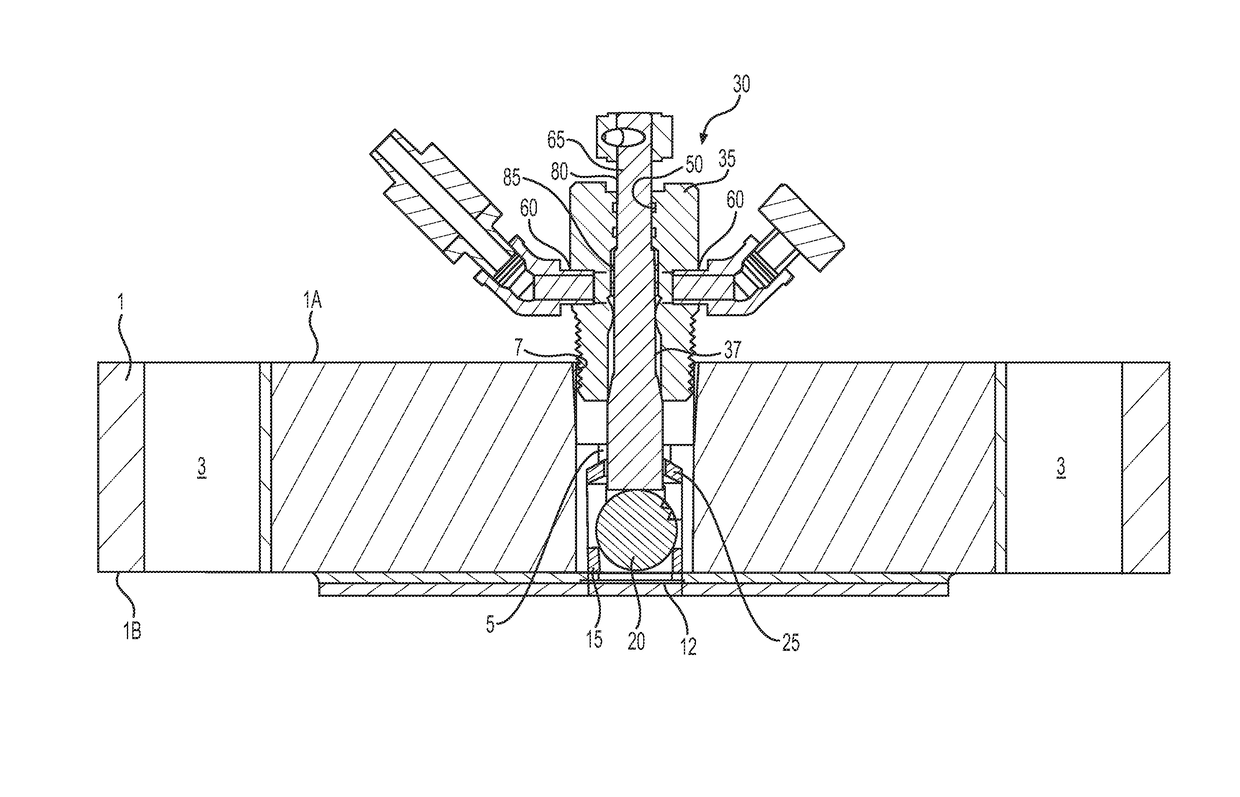
[0020]The present invention is intended for use in a pipeline containing oil, gas, or other potentially dangerous fluid, where it is important to know pressure in the pipeline prior to accessing the pipeline. The present invention provides an improved system and method for understanding and determining the pressure within a pipeline, thereby improving personnel and environmental safety. The present invention is designed to operate underground, above ground, or in a combination of locations, as may be needed depending upon the location of the pipeline and access points. The apparatus and methods provided will be better understood in view of FIGS. 1-6.

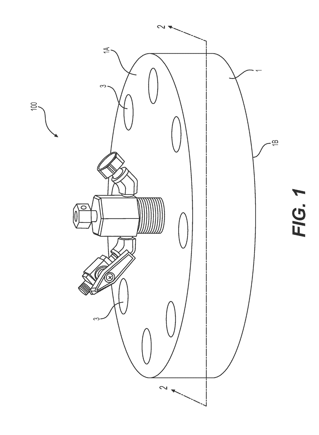
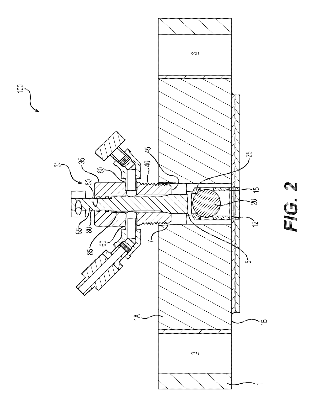
[0021]Referring initially to FIGS. 1-3, a pipeline inspection system 100 is provided comprising a flange body 1 having a first surface 1A, an opposing second surface 1B, and a bore 5 extending through the flange body 1 and between the flange body surfaces. The bore 5 may comprise a larger portion and a smaller portion, as shown in FIG. 3...


PUM


Abstract

The present invention relates to a system and method of inspecting and relieving pressure and fluid from a pipeline in a safe and environmentally friendly manner. An adjustable insert is placed within a flange of the pipeline, where the adjustable insert has a valve stem capable of moving into contact with a valve device to regulate fluid or gas from the pipeline and one or more outlets for relieving pressure or withdrawing fluid from the pipeline. The system and method provided are capable of operating in a closed process without loosening or removing a flange of the pipeline, thereby improving pipeline operator safety.

Description

CROSS-REFERENCE TO RELATED APPLICATIONS[0001]This application claims priority to U.S. Provisional Patent Application Ser. No. 62 / 222,649, filed on Sep. 23, 2015.TECHNICAL FIELD[0002]The present invention relates to a novel system that can be used in a safe and environmentally friendly manner to measure the pressure and remove the fluid behind a flange in a pipeline in a closed process without loosening or removing the flange, and to related methods to make and use the system.BACKGROUND OF THE INVENTION[0003]The efficient transportation of petroleum products (crude oil, gasoline, chemicals, natural gas) is critical to meeting the world's energy demands. Pipelines, rail cars, tankers, ships, and trucks all work in harmony in the transportation network to deliver energy to consumers. The most critical component of this network is the pipeline. North America alone depends on over 185,000 miles of liquid petroleum pipelines, 320,000 miles of gas transmission pipelines, and more than two ...

Claims


Application Information

Patent Timeline
IPC IPC(8): F17D1/20F17D3/10
CPCF17D3/10F17D1/20F16L41/008F16L45/00G01L19/0007G01M3/02Y10T137/6137
Inventor DICKE, TROY ALLENMOLMEN, STEVEN CLAYWAIDELICH, SHAWN ALLEN
Owner KPL SOUTH TEXAS LLC
Why Eureka
Try Eureka