
Backlight apparatus, control method therefor, and display apparatus

a backlight apparatus and control technology, applied in lighting apparatus, light sources, instruments, etc., can solve problems such as slow response speed, and achieve the effect of improving video viewing characteristics and reducing color gamut variation

Active Publication Date: 2016-04-12
CANON KK
View PDF14 Cites 0 Cited by
  • Summary
  • Abstract
  • Description
  • Claims
  • Application Information

AI Technical Summary

Benefits of technology

[0007]A backlight apparatus of the present invention uses light emitting elements that can provide white light illumination, reduces the variation in the color gamut due to the displayed brightness and improves video viewing characteristics.
[0009]According to the present invention, a backlight apparatus uses light emitting elements that can provide white light illumination, reduces the variation in the color gamut due to displayed brightness and improves the video viewing characteristics.

Problems solved by technology

This is caused by the slowness in the response speed of the liquid crystal molecules that are used in a liquid crystal panel.

Method used


Image

  • Backlight apparatus, control method therefor, and display apparatus
  • Backlight apparatus, control method therefor, and display apparatus
  • Backlight apparatus, control method therefor, and display apparatus

Examples


first embodiment

[0018

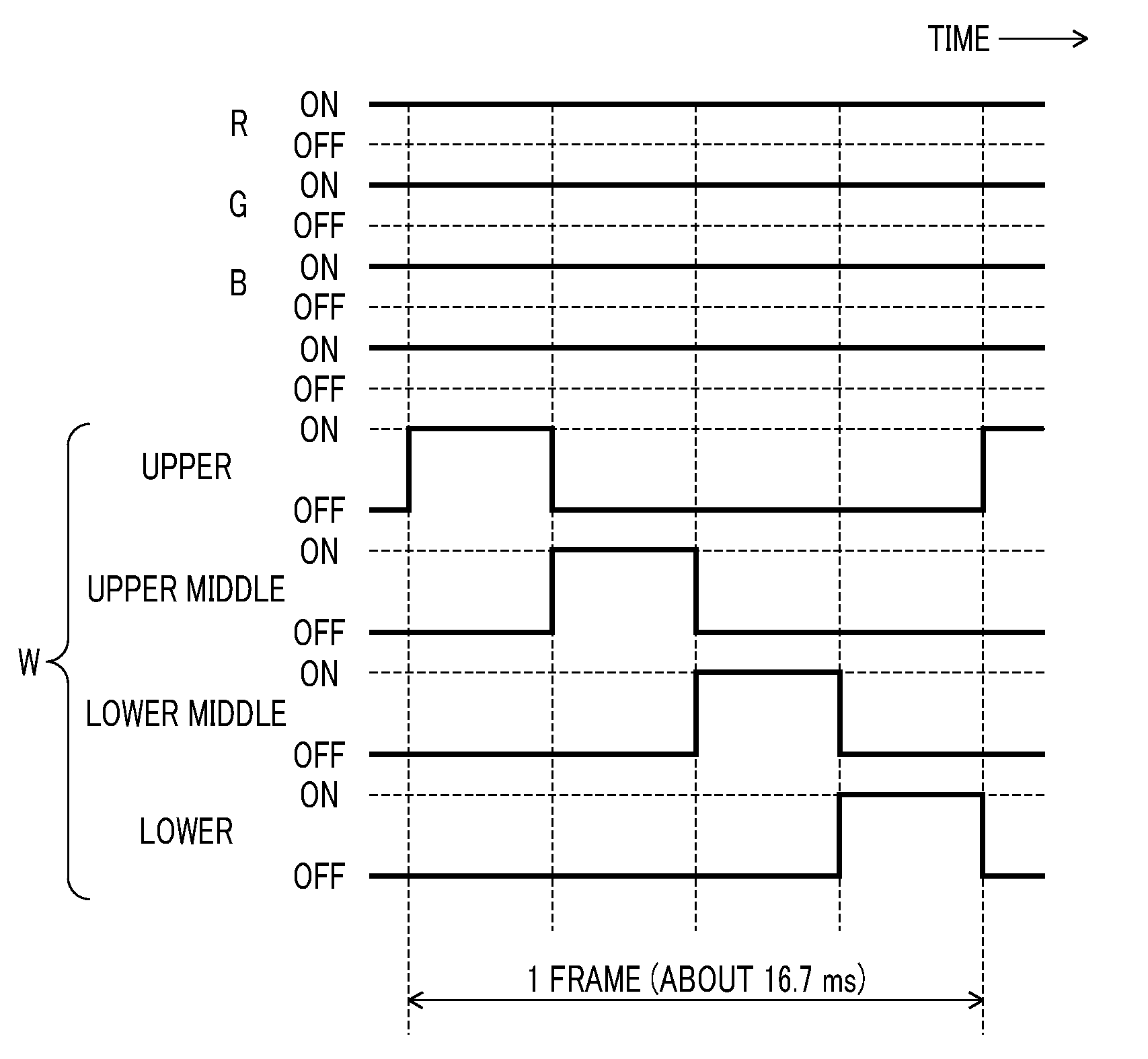
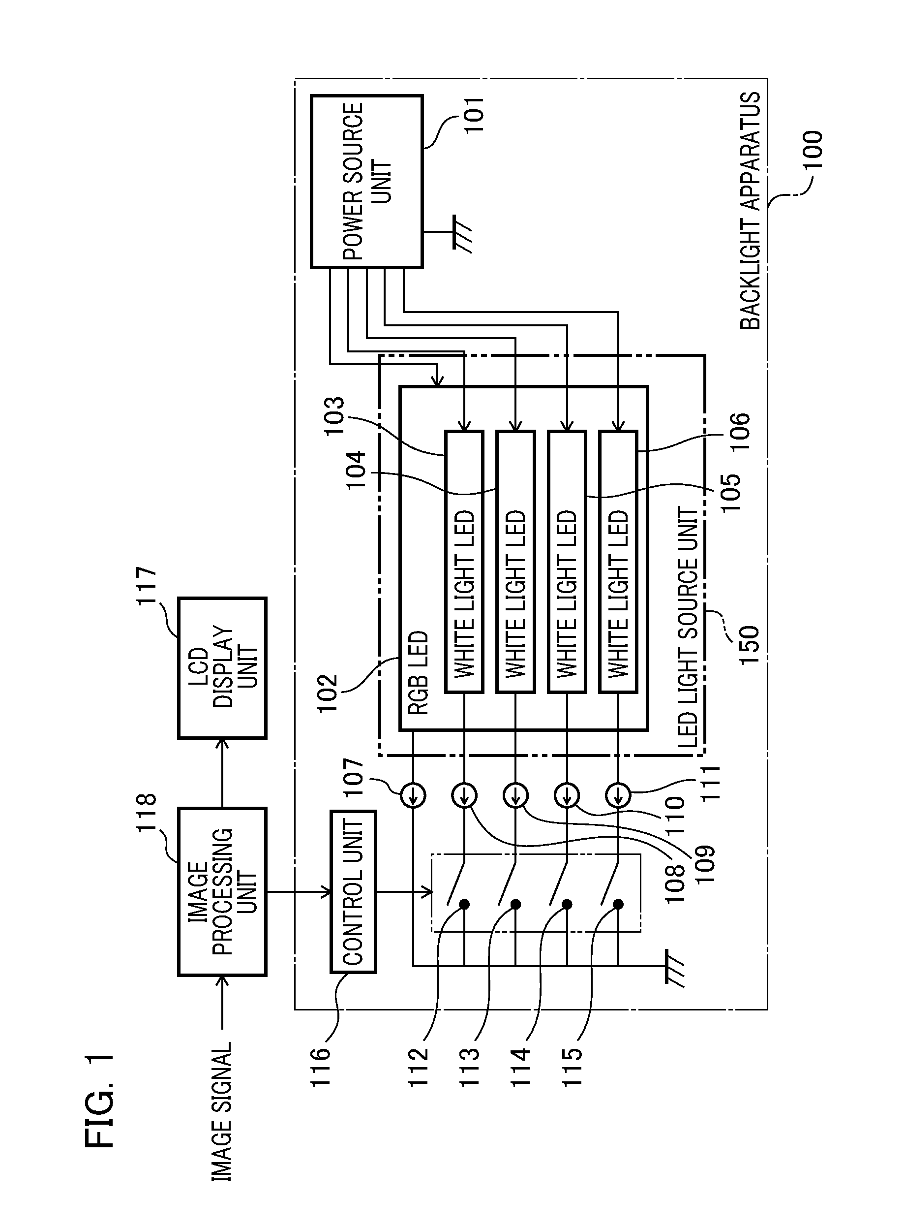
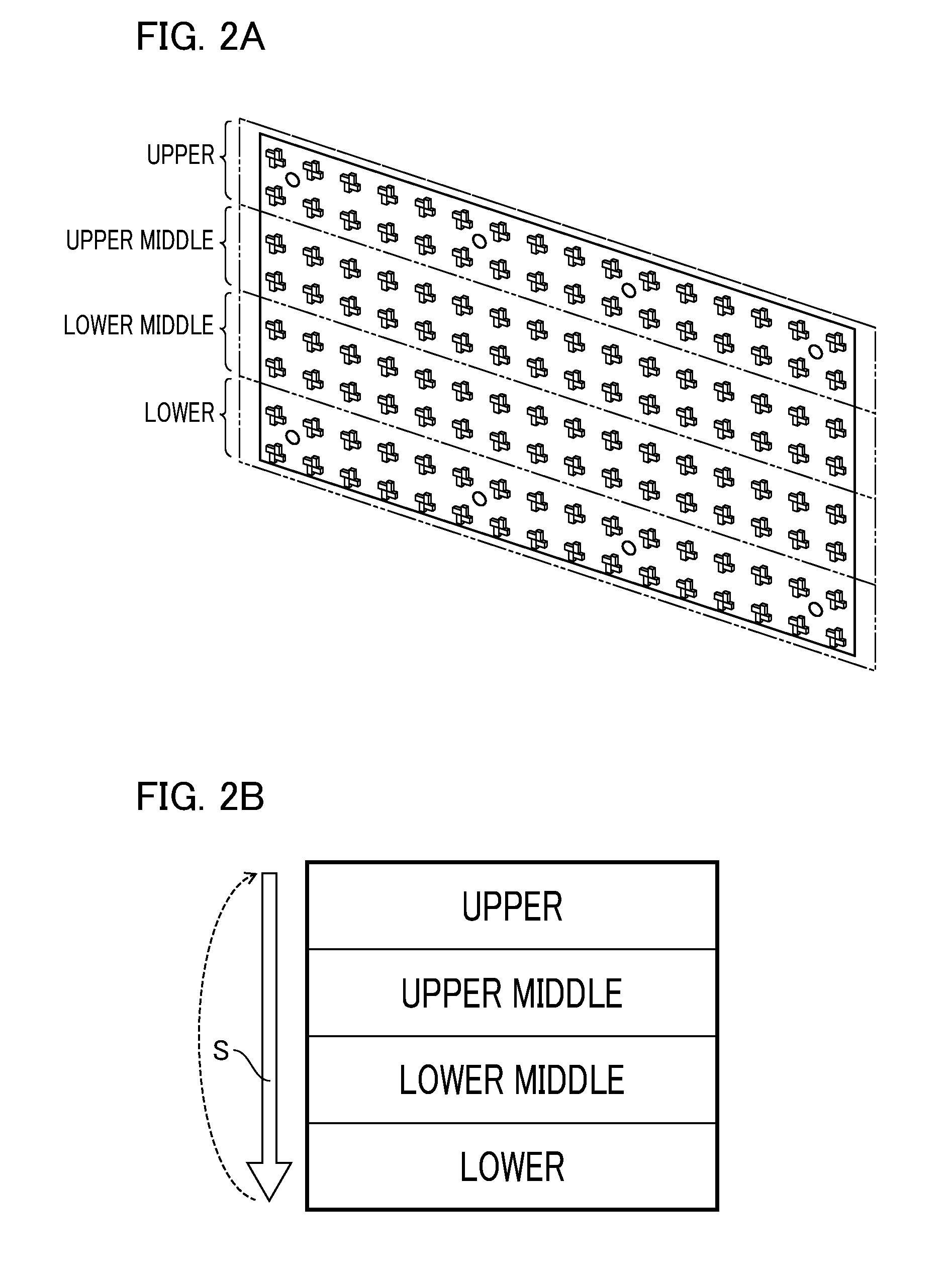
[0019]FIG. 1 is a block diagram that shows an example of a configuration of a backlight apparatus 100 according to a first embodiment of the present invention. In the backlight apparatus 100, the power source unit 101 supplies a power source voltage to each of the LEDs that is disposed in the LED light source unit 150. The LED light source unit 150 is an LED array substrate used in a backlight source. In this example, the first light source unit is provided with a plurality of white light LED light sources (white light LED units 103 to 106) that can individually provide white light illumination. In addition, the second light source unit is provided with an LED light source (below, referred to as the “RGB LED unit”) 102 that obtains white light by mixing RGB primary color light. That is, the first light source unit comprising light emitting elements that can provide white light illumination and the second light source unit comprising light emitting elements having properties tha...

second embodiment

[0032

[0033]Next, a second embodiment of the present invention will be explained. In the second embodiment, it is possible to select a first control mode (below, referred to as the “broad color gamut mode”) using the first embodiment and a second control mode (below, referred to as the “low power consumption mode”) that suppresses power consumption.

[0034]FIG. 4 is a block diagram that shows an example of the configuration of a backlight apparatus 300 according to the second embodiment. The difference between the second embodiment and the first embodiment is that the illumination control of LEDs disposed in the LED light source unit 350 can be switched by the mode switching unit 351. Thus, below, the point of difference between the first and second embodiments will be explained, and the explanations of identical parts will be omitted by using the reference numerals that have already been used for them.

[0035]In the present example, four LED units, 360 to 363, are provided, and these re...


PUM


Abstract

A light source unit that uses white light LEDs in a backlight apparatus is provided with a plurality of white light LEDs that can individually provide white light illumination. Each of the white light LED units respectively corresponds to partition areas in the vertical direction of the screen and is illuminated by scanning in sequence in conformity to the display screen of an LCD display unit. LED units that carry out white light display by RGB color mixing are continuously illuminated. In addition, in another embodiment, white light LEDs are continuously illuminated in a low power consumption mode, and ELD units that carry out white light display by RGB color mixing are illuminated by scanning in sequence in conformity to the display screen of the LCD display device.

Description

BACKGROUND OF THE INVENTION[0001]1. Field of the Invention[0002]The present invention relates to an illumination control technology for a backlight apparatus that uses light emitting elements that can display white light.[0003]2. Description of the Related Art[0004]In recent years, liquid crystal display (LDC) apparatuses have been developed as a display apparatus having a high definition, broad color gamut, and low power consumption. White light LEDs or LEDs that can display white light by mixing RGB colors and the like are used as light emitting diodes (below, abbreviated “LED”) in a light source unit for a backlight apparatus. During video display on liquid crystal display apparatuses, blurring occurs in the video image. This is caused by the slowness in the response speed of the liquid crystal molecules that are used in a liquid crystal panel. Japanese Patent Laid-Open No. 2000-321551 proposes a method in which the power supply to the LEDs of a backlight apparatus is stopped for...

Claims


Application Information

Patent Timeline
Patent Type & Authority Patents(United States)
IPC IPC(8): G09G3/36G09G3/34
CPCG09G3/3413G09G3/342G09G2310/0237G09G2320/0247G09G2320/0666G09G2330/021G09G2354/00G09G2310/024
Inventor MORISHITA, MASASHI
Owner CANON KK
Learn More