Coil assembly
a coil and assembly technology, applied in the direction of coils, electrical equipment, electrical relay details, etc., can solve the problem of inability to narrowly configure relays
- Summary
- Abstract
- Description
- Claims
- Application Information
AI Technical Summary
Benefits of technology
Problems solved by technology
Method used
Image
Examples
first embodiment
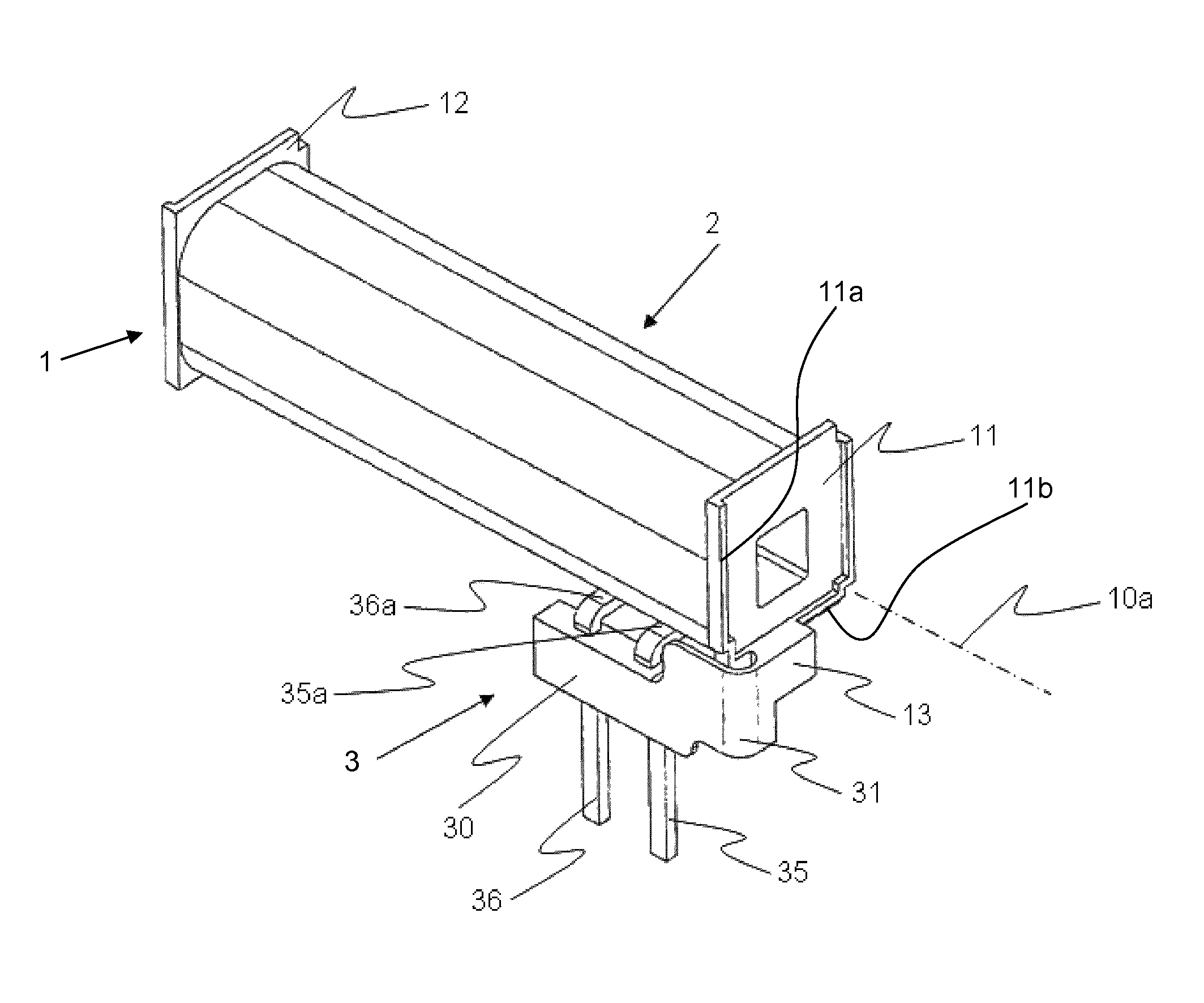
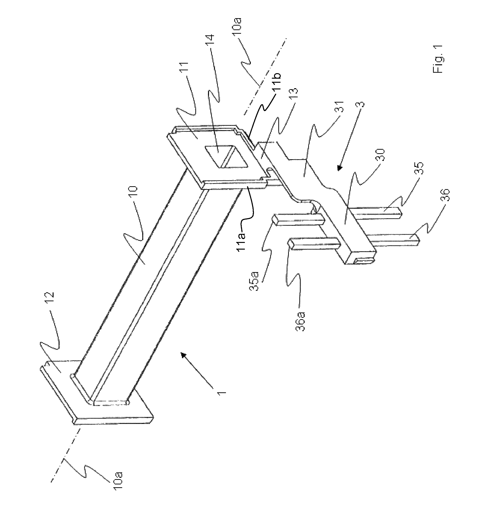
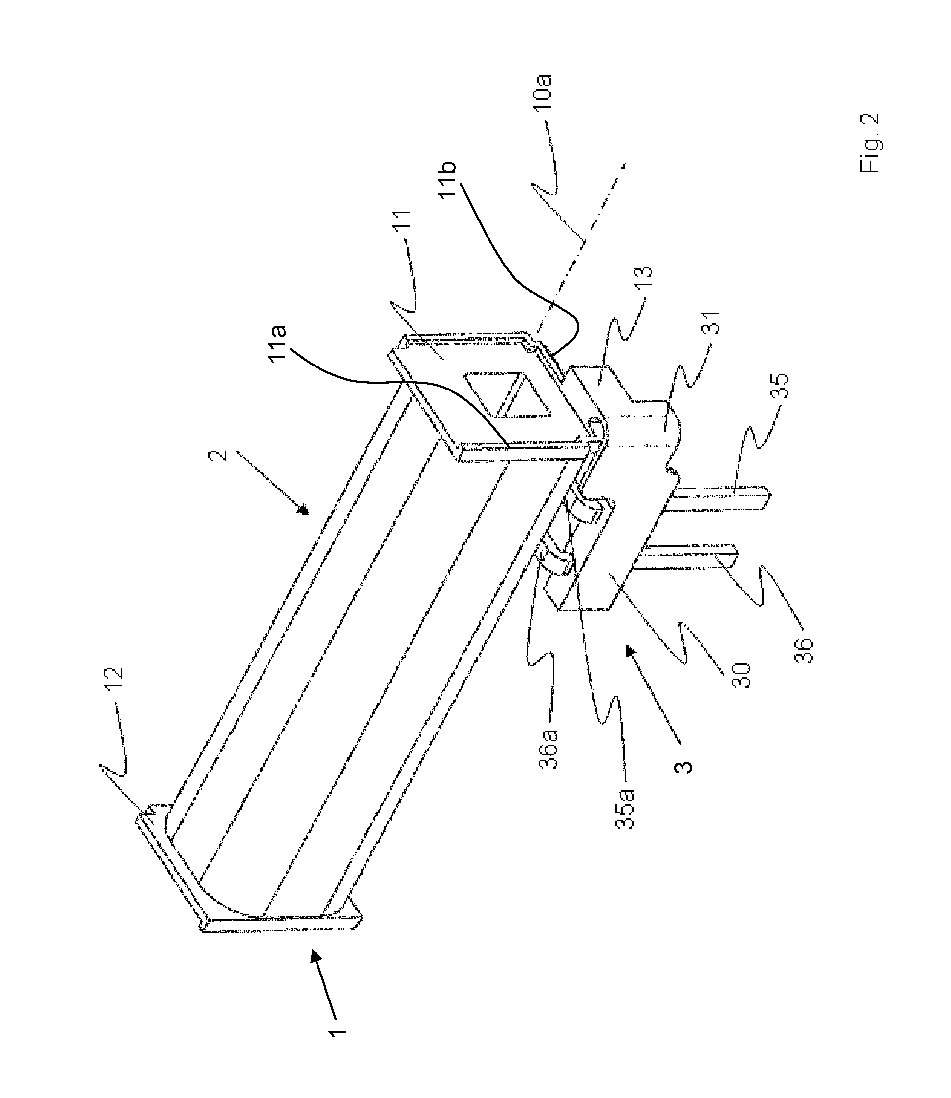
[0020]FIGS. 1 and 2 show a coil assembly according to the invention. The main parts of the coil assembly are an insulating coil former 1, a coil 2, and a connection block 3 which can be pivoted from a preparatory position as seen in FIG. 1 to a final position as seen in FIG. 2. The coil former 1 has a coil tube 10 with a longitudinal cavity 14 which define a coil axis 10a, and two flanges 11 and 12 at the ends of coil tube 10. Flange 11 has peripheral edges, and the pivoting of connection block 3 is effected in extension of peripheral edge 11a. An extension 13 is secured to peripheral edge 11b of flange 11 and is integrally joined to connection block 3. Connection block 3 comprises an insulating block body 30 and a flexible deformable hinge portion 31 on the extension of peripheral edge 11a. Coil former 1 with flange extension 13, hinge portion 31, and block body 30 are made of electrically insulating material which is suitable for overmolding metallic parts. Such metallic parts are...
fourth embodiment
[0025]FIGS. 7 and 8 show the invention.
[0026]The same reference numerals as before are used. Extension 13 on coil connection flange 11 has a downwardly extending projection 13a for accommodating a torsion leg 38a of an elbow-shaped joining member 38. The angled leg of joining member 38 extends into and is anchored in block body 30. In the preparatory position as seen in FIG. 7, the main plane of connection block 3 extends transversely to the coil axis 10a, and in this preparatory position the coil 2 is wound, whereupon the winding wire ends 21, 22 are soldered or otherwise conductively connected to their respective terminal pins 35, 36. Thereafter, connection block 3 is pivoted from the position of FIG. 7 into the position of FIG. 8, whereby the torsion leg 38a of the elbow-shaped joining member 38 is twisted and undergoes permanent deformation.
PUM
| Property | Measurement | Unit |
|---|---|---|
| flexible | aaaaa | aaaaa |
| length | aaaaa | aaaaa |
| magnetic | aaaaa | aaaaa |
Abstract
Description
Claims
Application Information
 - R&D
- Intellectual Property
- Life Sciences
- Materials
- Tech Scout
- Unparalleled Data Quality
- Higher Quality Content
- 60% Fewer Hallucinations
Browse by: Latest US Patents, China's latest patents, Technical Efficacy Thesaurus, Application Domain, Technology Topic, Popular Technical Reports.
© 2025 PatSnap. All rights reserved.Legal|Privacy policy|Modern Slavery Act Transparency Statement|Sitemap|About US| Contact US: help@patsnap.com


