Picking arrangement

a technology of picking arrangement and arranging parts, which is applied in the direction of picking devices, mowers, agriculture tools and machines, etc., can solve the problems of sinking of the harvester into the ground, weakening of the ground structure, etc., and achieve the effect of reducing the number of parts and the number of installation steps

Inactive Publication Date: 2018-04-17
KALVERKAMP KLEMENS DE +1
View PDF13 Cites 0 Cited by
  • Summary
  • Abstract
  • Description
  • Claims
  • Application Information

AI Technical Summary

Benefits of technology

[0015]According to an embodiment of the present invention, the longitudinal axis of the picking gap may be oriented transversely or substantially transversely or approximately transversely to the working direction. The longitudinal axis of the picking gap may be oriented in parallel with or substantially in parallel with or approximately in parallel with the ground. A relatively short configuration of the picking apparatus in the working direction is also hereby possible.
[0025]The blades can be of a rigid design. The blades may also be resilient and have a greater curvature about the screw axis in the relaxed state than a jacket surface, in particular a notional jacket surface, of the cutting screw conveyor. This ensures that the blades and the cutting screw conveyor are tensioned with respect to one another during the cut to improve the cutting result. The screw channel presses against the blades during the rotation of the cutting screw conveyor so that said blades are tensioned while reducing their curvature. On a further rotation of the cutting screw conveyor, the screw channel then again allows a springing back of the blades, with the tensioning and relaxing of the blades periodically repeating with a rotating cutting screw conveyor. The blades may consist of spring steel.
[0030]In another embodiment, at least one guide is fixedly connected to the holder. The guide is disposed higher than the conveying device and / or the screw axis. The separated plants may be guided by the guide. The separated plants can be supported to the front by the guide. The separated plants can also be supported against a falling forward at or by means of the guide. The guide may be arranged in front of the conveying direction and / or of the screw axis so that the separated plants can be guided between the guide and the conveying device and / or the cutting screw conveyor. The guide can prevent the plants from falling forward. The guide may be disposed higher than the conveying device and / or the screw axis with respect to the ground. If the cutting screw conveyor is rotating upwardly as viewed from the front, this also counteracts a falling forward of the separated plants; however, a better protection against the falling forward of the separated plants can be achieved using the guide.
[0031]In yet another embodiment, the guide extends in the conveying direction and / or along the screw axis. The separated plants can thus be prevented from falling forward by the guide during their transport and / or their conveying. The guide may be provided with a plurality of passage openings which are arranged at a spacing from one another in the conveying direction and / or along the screw axis. The passage openings allow plants to enter into the space between the guide and the conveying device and / or the cutting screw conveyor from the front or to move behind the guide.
[0034]The guide elements may each comprise an upwardly extending and / or vertical lower section and an upper section which extends in the direction of the screw axis and / or which is horizontal, which can also be called a guide section and which also adjoins the lower section. The guide elements, preferably their upper sections, may be inclined, curved and / or angled at least regionally, in their upper regions, in the conveying direction and / or in the direction of the screw axis. The upper section may prevent a falling forward of the separated plants. The guide elements are formed as extensions of the blades and / or of the divider tips. A reduction of components and installation steps in the production of the picking apparatus may thus be achieved. The guide elements may each comprise a free end, such as an upper free end. The free end of each guide element may be provided at its upper section. Each of the guide elements, in particular the lower section thereof, may be fixedly connected to the holder at the bottom and / or each of the guide elements, in particular the lower section thereof, merges at the bottom into one of the blades and / or into one of the divider tips.
[0035]In the conveying direction and / or in the direction of the screw axis, two adjacent guide elements may overlap in the passage opening disposed between them. The upper sections of the adjacent guide elements may overlap. Two adjacent guide elements each form a guide element pair. The guide elements of each guide element pair, in particular their upper sections, may overlap in the direction of the screw axis in the passage opening disposed between them. When each guide element pair is viewed in the conveying direction, the guide element at the rear engages behind the guide element at the front. This overlapping and / or engaging behind of the guide elements prevents separated plants from falling forward through the passage opening.

Problems solved by technology

A high axle load may result in a weakening of the ground structure and / or in a sinking of the harvester into the ground.

Method used


Image

  • Picking arrangement
  • Picking arrangement
  • Picking arrangement

Examples


first embodiment

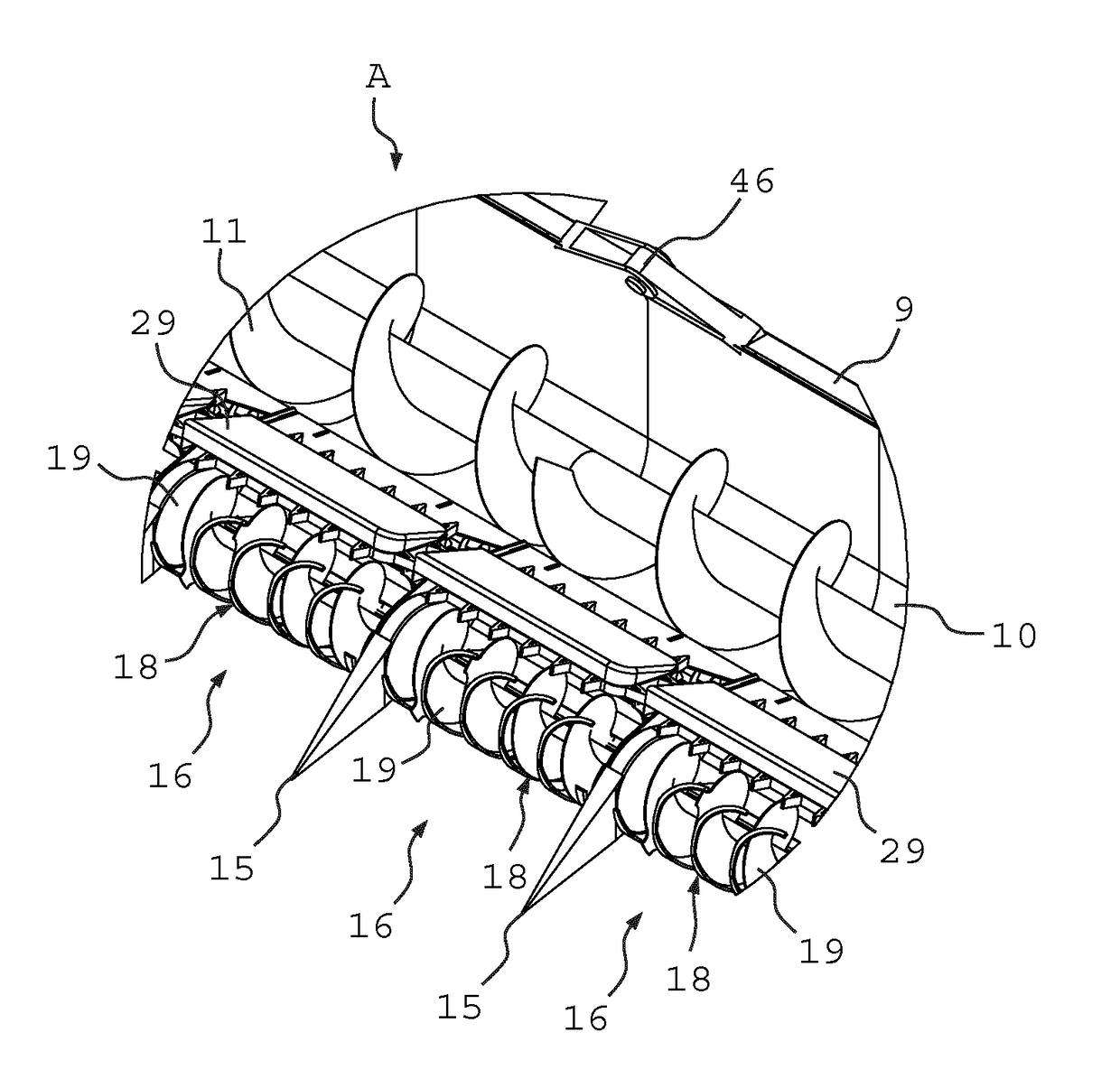
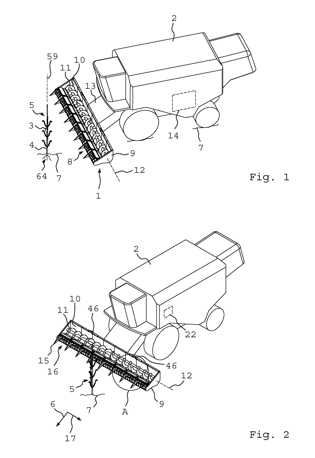
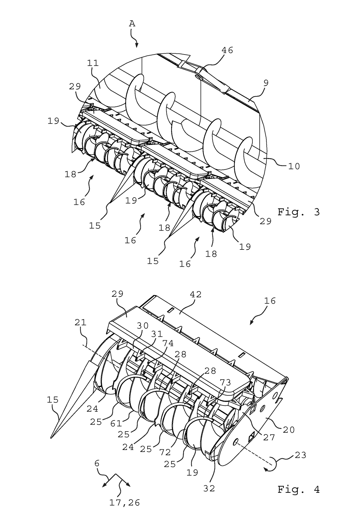
[0070]FIGS. 1 and 2 provide perspective views of a picking arrangement in the form of a picking attachment 1 which is fastened to the front of a harvesting vehicle 2. The picking attachment 1 picks plant product 3 which is seated on elongate stalks 4 of plants 5 which are anchored in the ground 7 by roots 64. Non-limiting examples of produce / plant product may include fruit, seed head such as corn cob, sunflower capitulum / inflorescence etc. The stalks 4 each have a pronounced longitudinal direction 59 which extends upward from the ground 7. The picking attachment 1 is moved along the ground 7 in a working direction 6 by the harvesting vehicle 2 so that the plants 5 come into contact with a conveying unit 8 of the picking attachment 1 and are gathered by the conveying unit 8. The working direction 6 may be the forward direction of travel of the harvesting vehicle 2. The picking attachment 1 consists of a carrier construction 9 to which a trough 10 is fastened in which a transverse scr...

third embodiment

[0083]A perspective view of a picking apparatus 16 of the invention can be seen in FIG. 11, with the conveying device 18 being formed by a gripping cutter 48. The gripping cutter 48 is configured as a chain conveyor at whose chain a plurality of grippers 49 are provided which are arranged at a spacing from one another and which each have a cutting edge 50. The grippers 49 grip the stalks of the plants and transport them in a transverse direction 17, with the cutting edges 50 cooperating with blades 51 fastened to the holder 20 for cutting the stalks. The cut off plants are then supplied to the transfer region 27 by the grippers 49 and the fingers 31, with the conveying direction 26 of the gripping cutter 48 coinciding with the transverse direction 17. The plants are then supplied to the rear to the picking gap 34 by the grippers 49 and the fingers 31.

[0084]A perspective view of a picking apparatus 16 of a fourth embodiment of the invention can be seen in FIG. 12, wherein the lateral...

fifth embodiment

[0085]A picking apparatus 16 of the invention can be seen in FIG. 13, wherein the auxiliary transport apparatus 29 is formed by a plurality of screw conveyors 54, 55. The screw conveyors 54 and 55 are each supported at the holder 20 rotatable about an axis of rotation 56 and 57 respectively. The screw conveyors 54 and 55 are driven by the drive 22 and thus rotate about their axes of rotation 56 and 57 respectively. The screw conveyor 54 assists the conveying device 18 formed by the cutting screw conveyor 19, whereas the screw conveyor 55 transports the plants seated in the picking gap in the longitudinal direction of the picking gap and indeed in a direction opposite to the conveying direction 26 of the conveying device 18.

[0086]A sectional view through the cutting screw conveyor 19 along the line D-D of FIG. 6 can be seen in FIG. 14, which illustrates a modification of the first embodiment. In contrast to the first embodiment, the blades 25 are resilient and have a greater curvatur...


PUM


Abstract

A picking apparatus having at least one holder movable in a working direction. The holder has at least one conveying device with a front gathering region. The produce bearing plants come in contact with the conveying device in the front gathering region. The conveying device is operable to gather and transport plants in at least one conveying direction. The conveying direction extend in a straight or substantially straight line and transverse or substantially transverse to the working direction. The picking apparatus also has a picking gap defined behind the conveying device, wherein the plants are guided through the picking gap while separating the produce.

Description

CROSS-REFERENCE TO RELATED APPLICATIONS[0001]This application claims priority to international patent application Serial No. PCT / EP2014 / 061554, filed Jun. 4, 2014, which claims priority to international patent application Serial No. DE 10 2013 106 197.4, filed Jun. 13, 2013, the contents of which are incorporated herein in their entirety.FIELD OF THE INVENTION[0002]The invention relates to a picking apparatus comprising at least one holder which is movable in a working direction and has at least one conveying device with a front gathering region which brings the conveying device into contact with produce-bearing plants by moving the holder in the working direction so that the plants can be gathered by the conveying device and can be conveyed in at least one conveying direction such that the plants are separated from the produce by guiding the plants through a picking gap in the conveying device.BACKGROUND OF THE INVENTION[0003]DE 197 34 747 A1 discloses a corn harvesting attachment ...

Claims


Application Information

Patent Timeline
Patent Type & Authority Patents(United States)
IPC IPC(8): A01D46/00A01D45/00A01D57/00A01D34/53A01D45/02
CPCA01D46/00A01D34/53A01D57/00A01D45/021A01D45/00
Inventor KALVERKAMP, KLEMENSKALVERKAMP, FELIX
Owner KALVERKAMP KLEMENS DE
Why Eureka
Try Eureka