
Motor gearbox unit

a technology for motor gearboxes and gearboxes, which is applied in the direction of mechanical energy handling, dynamo-electric components, and control/drive circuits. it can solve the problems of disadvantageous robustness and complicated mounting of known housings, and achieves sufficient moisture-proof properties, increased robustness, and improved stability.

Inactive Publication Date: 2011-09-01
ROBERT BOSCH GMBH
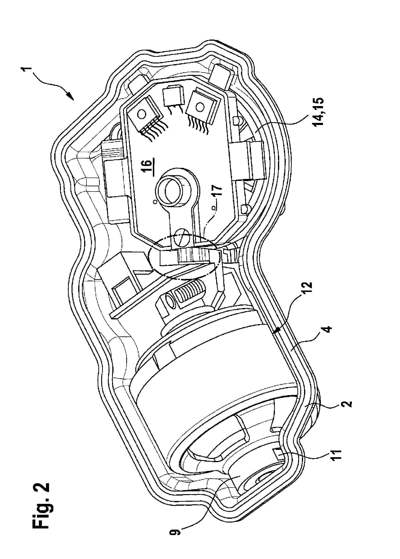
View PDF9 Cites 0 Cited by
  • Summary
  • Abstract
  • Description
  • Claims
  • Application Information

AI Technical Summary

Benefits of technology

[0005]The invention is based on the concept of providing a common housing, which is configured as a shell housing, for the electric motor and the gearbox of the motor gearbox unit, which gearbox can be driven by the electric motor and is preferably configured as a worm gear mechanism. The mounting of the motor gearbox unit is facilitated considerably and additionally the robustness is increased by the provision of a common housing, which is configured as a shell housing, for the electric motor and the gearbox. Here, there is a very wide variety of possibilities for fixing the two shell parts to one another. One embodiment is particularly preferred, in which the two shell parts are crimped to one another; it is particularly preferred, in order to ensure a sufficient moisture-proof property, to provide a circumferential annular seal between the shell parts, which annular seal is preferably configured as a flat seal.
[0010]In a development of the invention, there is advantageously provision for the pole casing of the electric motor to be in linear contact with the second shell part, the contact line preferably extending parallel to the longitudinal extent of the pole casing. The linear contact between the pole casing and the second housing part makes it possible for the pole casing to be of particularly short configuration and to be arranged without stress. It is possible as a result of the linear mounting to compensate for any length tolerances between the skeleton motor and the shell part by linear displacement of the holding part / pole casing unit (motor unit). The spatial position of the armature shaft of the skeleton motor is defined unambiguously in relation to the second shell part on account of the linear mounting.

Problems solved by technology

The complicated mounting and the robustness which is in need of improvement of known housings are disadvantageous.

Method used


Image

  • Motor gearbox unit
  • Motor gearbox unit
  • Motor gearbox unit

Examples


Embodiment Construction

[0043]In the figures, identical elements and elements with the same function are labeled with the same designations.

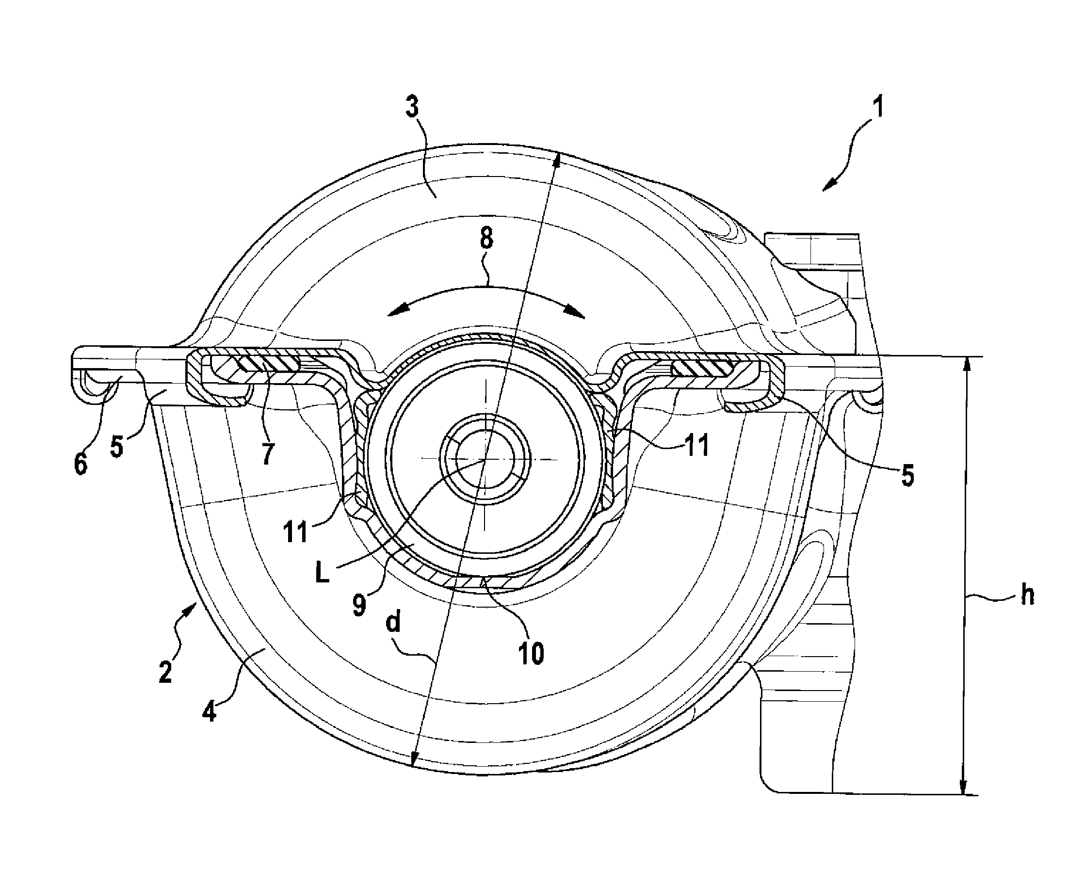
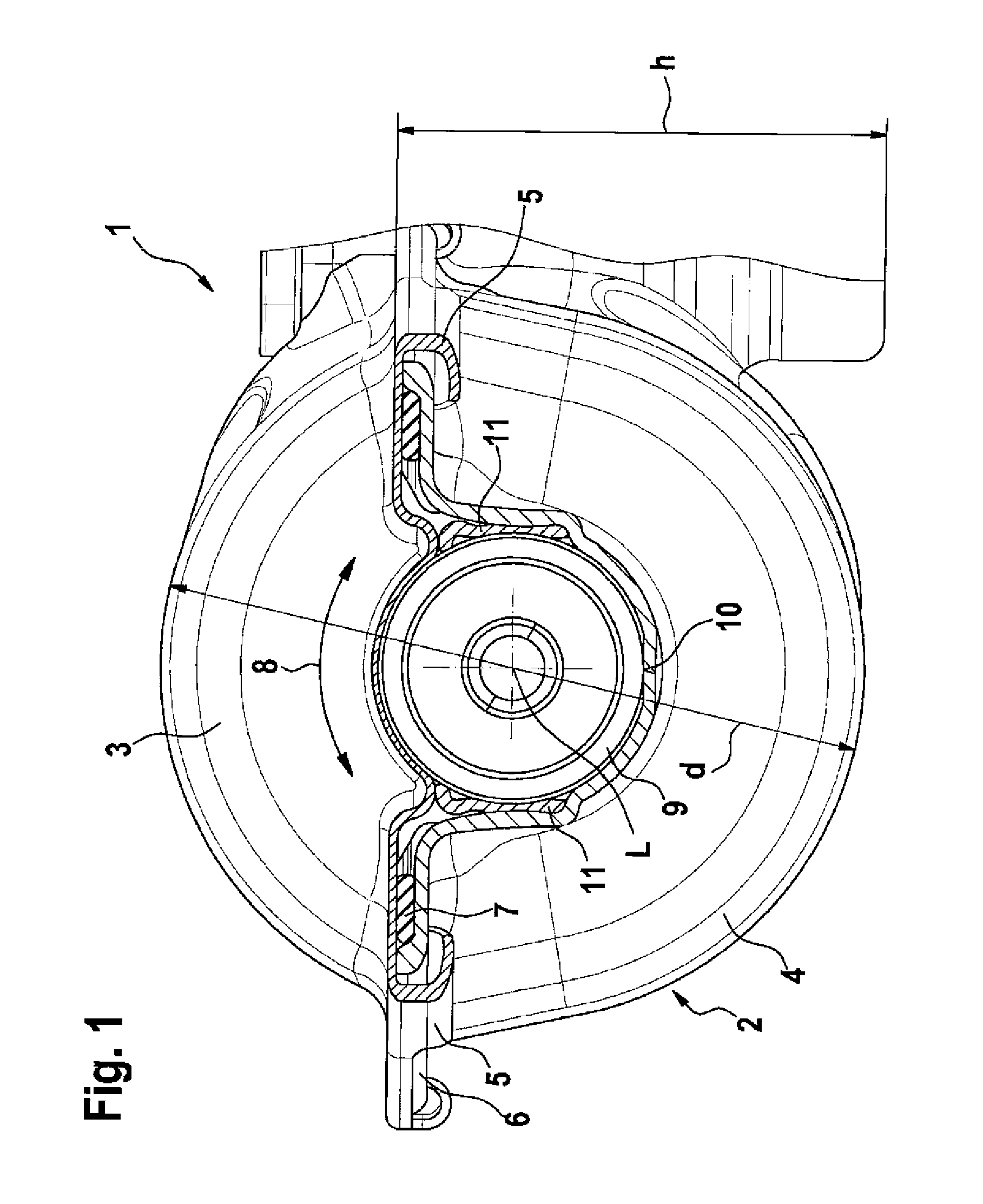
[0044]FIG. 1 shows a partially sectioned view of a motor gearbox unit 1 for a pane wiping assembly which is otherwise not shown in greater detail. The motor gearbox unit 1 is provided with a housing 2 which is configured as a two piece shell housing and has a first shell part 3 which serves as housing cover and a second shell part 4 which is connected to the first shell part 3 and is configured as a lower shell for accommodating all the electric motor and gearbox components.

[0045]It can be seen from FIG. 1 that the two shell parts 3, 4 are crimped to one another. To this end, the first shell part 3 has edge-side brackets 5 which are arranged so as to engage behind a circumferential fastening flange 6 of the second shell part 4. An annular seal 7 which is configured as a flat seal and ensures the pressure tightness of the housing 2 is situated between the two shell part...


PUM


Abstract

The invention relates to a motor gearbox unit (1), particularly for a windshield wiper system in a motor vehicle, comprising an electric motor (12) and a gearbox (14) driven by the electric motor (12), and a housing (2). According to the invention, the housing 2) is designed as a shell housing receiving both the electric motor (12) and the gearbox (14) and comprises a first and a second shell part (3, 4).

Description

BACKGROUND OF INVENTION[0001]The invention relates to a motor gearbox unit, in particular for a pane wiping assembly in a motor vehicle.[0002]Housings which have previously been used in practice for motor gearbox units for pane wiping assemblies comprise a pole pot of an electric motor, which pole pot is flange connected laterally to a two piece gearbox housing. The complicated mounting and the robustness which is in need of improvement of known housings are disadvantageous.[0003]Furthermore, it is known to use shell housings which are formed from two symmetrical half shells exclusively for electric motors, in which the individual functions such as mounting, positioning and tolerance compensation are divided equally among both shells.SUMMARY OF THE INVENTION[0004]The invention is based on the object of proposing a motor gearbox unit of alternative construction. This should preferably be capable of being mounted comparatively simply and adapted universally to application specific req...

Claims


Application Information

Patent Timeline
IPC IPC(8): H02K7/116H02K11/00H02K5/22
CPCH02K5/04H02K5/10H02K23/66H02K7/1166H02K11/0073H02K5/146H02K11/33H02K7/116
Inventor KASTINGER, GUENTERHUESGES, MARIOOBERT, MIKELAUK, DETLEFRIEDINGER, KLAUS
Owner ROBERT BOSCH GMBH
Learn More