Supercharge Your Innovation With Domain-Expert AI Agents!

Energy store and energy storage system

a technology of energy storage and energy storage, applied in the direction of secondary cell servicing/maintenance, cell components, cell component details, etc., can solve the problems of affecting the current consumption of the control unit, and affecting the performance of the energy stor

Active Publication Date: 2016-04-12
ROBERT BOSCH GMBH
View PDF10 Cites 4 Cited by
  • Summary
  • Abstract
  • Description
  • Claims
  • Application Information

AI Technical Summary

Benefits of technology

[0006]The present invention is based on the objective of indicating an energy store and an energy storage system, which allows the energy store to be stored even for a longer period.
[0009]Storing the energy store outside of a device for the exchange of energy is thus unproblematic. It is thus possible to maximize an energy obtainable by the device from the energy store. This also makes it possible to use in the construction of the control unit that are not characterized by particularly low energy consumption or a particularly power-saving mode (“sleep mode”). A selection of components may thereby be simplified and the manufacturing costs for the control unit may be lowered.
[0012]The first conductive element may be developed to transmit energy between the device and the accumulator. The first conductive element may be a charging terminal of the accumulator such that compared to a known chargeable energy store an additional expenditure may be limited to the second element. This makes it possible to keep the costs of development and manufacturing for the energy store low.
[0014]In this specific embodiment, the number of conductive elements on the interface may be left unchanged. This makes it possible to reduce a danger of an unintentional contacting or short-circuiting of conductive elements of the interface.
[0015]In both of the described specific embodiments, the control unit may have another supply voltage terminal, which is permanently connected to the accumulator. The activation or deactivation of the control unit via the switch or via the conductive elements is thus limited to only one of the supply voltage terminals. The additional supply voltage terminal may be connected to a ground terminal of the accumulator. The switched supply voltage terminal of the control unit thus concerns a positive supply voltage. This construction is customary and particularly simple, which further allows manufacturing costs to be kept low.

Problems solved by technology

A current consumption of the control unit, however, occurs even when the energy store is not connected to a device.
In the course of a longer storage period, the performance of the energy store may be impaired by the discharging of the control unit.
In unfavorable circumstances, the accumulator of the energy store may even be exhaustively discharged by the control unit and thus damaged or even destroyed.
Storing the energy store outside of a device for the exchange of energy is thus unproblematic.

Method used


Image

  • Energy store and energy storage system
  • Energy store and energy storage system
  • Energy store and energy storage system

Examples


Embodiment Construction

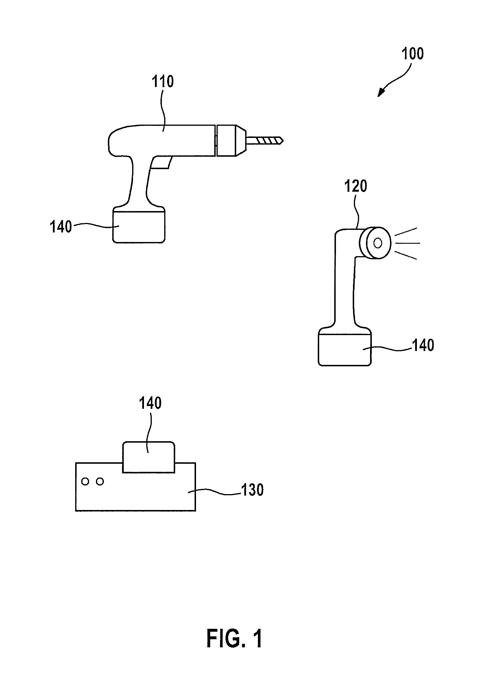
[0021]FIG. 1 shows a system 100 of different devices. The system includes a battery-operated screwdriver 110, a lamp 120 and a charger 130 as well as a number of energy stores 140. An energy store in the form of a battery pack 140 is attached on each one of devices 110 through 130. Battery-operated screwdriver 110 and lamp 120 represent electrical consumers, which are operable by the electrical energy stored in battery pack 140. Charger 130 is used to store electrical energy in battery pack 140 for later withdrawal by one of the consumer devices 110 or 120.

[0022]Battery pack 140 is mechanically and electrically developed to be connected to each one of devices 110 through 130. If more than only one battery pack 140 is available, then at least one of consumer devices 110, 120 may be used with one of battery packs 140, while at the same time another battery pack 140 is being charged in charger 130. If required, additional battery packs 140 may be kept in reserve in a charged state for ...


PUM

PropertyMeasurementUnit
exchange of energyaaaaaaaaaa
energyaaaaaaaaaa
areaaaaaaaaaaa

Abstract

A chargeable energy store includes a chargeable electrical accumulator, an interface for connecting the accumulator to a device for the exchange of energy and a control unit for controlling the energy exchange of the accumulator. The control unit includes a supply voltage terminal, which is connected to the accumulator when a device is connected to the interface for the exchange of energy, and which is otherwise disconnected from the accumulator.

Description

FIELD OF THE INVENTION[0001]The present invention relates to a chargeable electrical energy store and to a system having the energy store.BACKGROUND INFORMATION[0002]In the area of small electrical devices it is customary to use electrical energy stores that are separable from the small device in order to be recharged. During the charging process, an additional energy store may be inserted into the small device such that the latter may continue to be operated during the charging process. Frequently it is also possible to use the energy store interchangeably in different small electrical devices, for example in a battery-operated screwdriver and in a lamp.[0003]Known energy stores include a control unit, which monitors both a charging process as well as a discharging process of the energy store. This is to improve an energy management and reduce the danger of damaging or destroying one of the devices or the energy store due to incorrect charging or discharging. The control unit is de...

Claims


Application Information

Patent Timeline
Patent Type & Authority Patents(United States)
IPC IPC(8): H02J7/00H01M10/44H01M10/42H01M2/34H01M50/574
CPCH01M2/34H01M10/4257H01M10/44H02J7/0068H02J7/0063H02J2007/0067Y02E60/10H02J7/007186H01M50/574
Inventor CLAUS, HOLGER
Owner ROBERT BOSCH GMBH
Features
  • R&D
  • Intellectual Property
  • Life Sciences
  • Materials
  • Tech Scout
  • Unparalleled Data Quality
  • Higher Quality Content
  • 60% Fewer Hallucinations
Learn More