
Optical information recording medium

a technology of optical information and recording medium, which is applied in mechanical recording, instruments, and thermography, etc., can solve the problems of difficult to accurately read the data recorded on the optical information recording medium, difficult to obtain the desired tilt margin, and a large thickness of the substrate, so as to reduce the noise level and improve the c/n ratio

Active Publication Date: 2007-01-23
TDK CORPARATION
View PDF5 Cites 41 Cited by
  • Summary
  • Abstract
  • Description
  • Claims
  • Application Information

AI Technical Summary

Benefits of technology

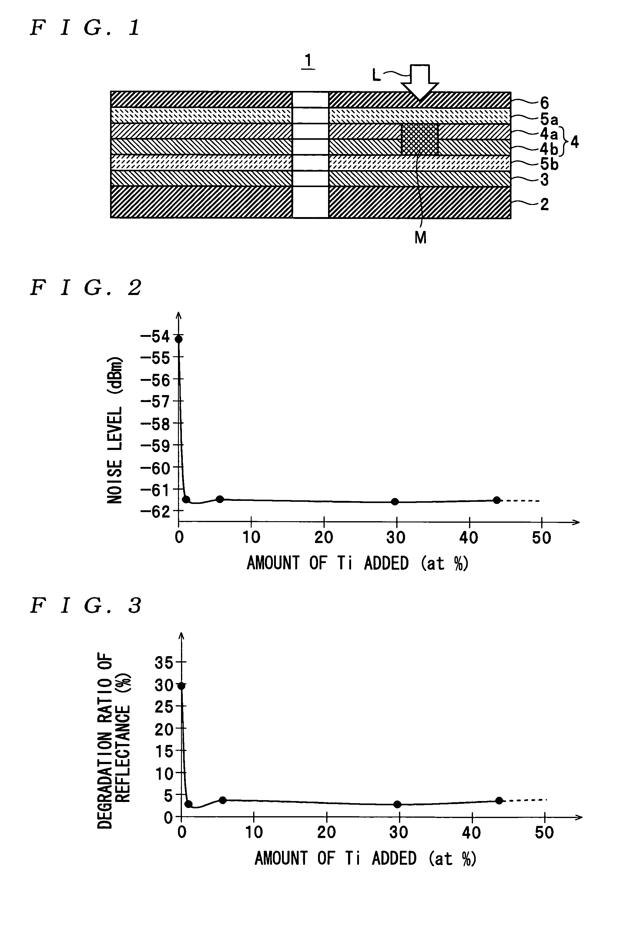
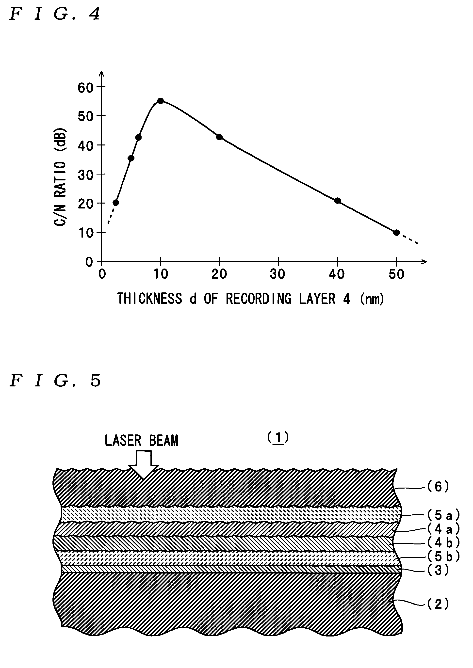
The present invention provides an optical information recording medium that can reduce noise levels, improve C / N ratio, and store record data for a long time period. This is achieved by using a recording layer with two main recording films, one containing Si and the other containing Al with added Ti, which improves surface smoothness and reduces noise levels. The addition of Ti also enhances the degradation ratio of reflectance, allowing for high-density recording and long-term storage of record data. The recording layer is preferably formed with the two main recording films in contact with each other, and a total thickness of the two films should be not less than 2 nm and not more than (40 nm to further enhance the C / N ratio and reliably reproduce the record data. The optical information recording medium can also include a reflective layer and / or dielectric layers to prevent thermal deformations and increase the difference in optical reflectance between recorded and unrecorded portions.

Problems solved by technology

Therefore, in the case of the construction of the optical information recording medium, such as a conventional general type, in which the laser beam emitted from the pickup is irradiated through the substrate to the recording medium, the substrate has a rather large thickness of e.g. approximately 1 mm, and therefore it is difficult to obtain a desired tilt margin.
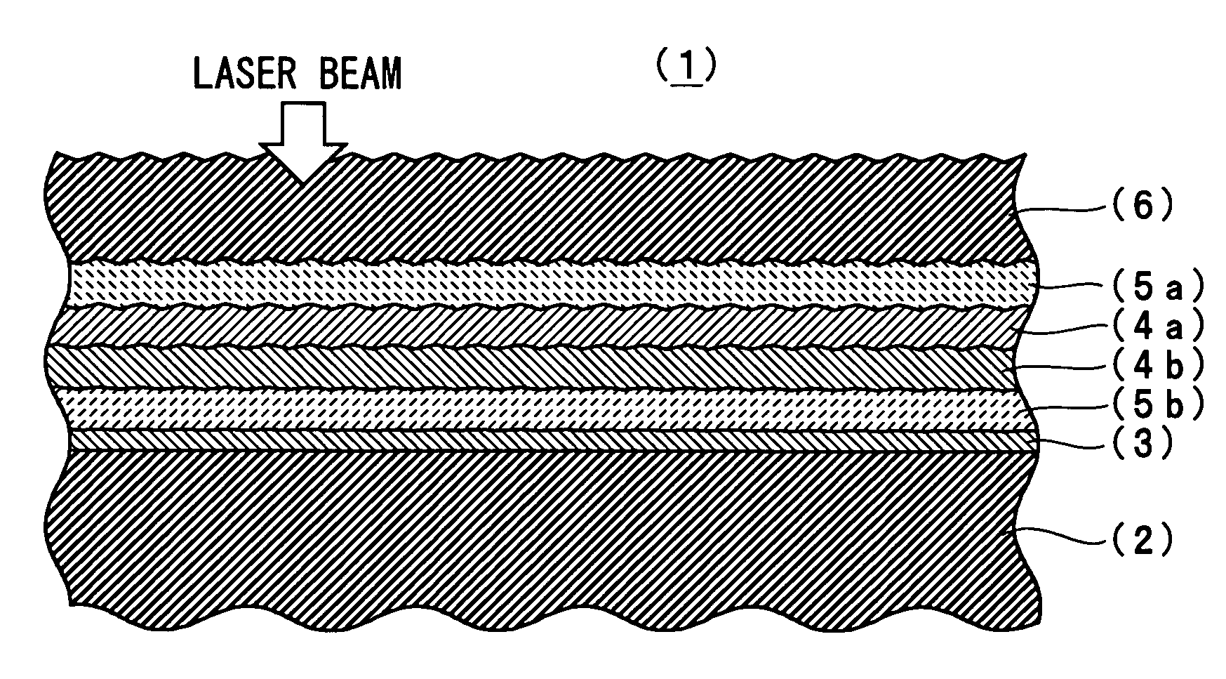
Therefore, depending on the reproduction speed, it can be difficult to accurately read record data recorded on the optical information recording medium (1), since the surface of each layer thereof tends to be formed to be rougher as the layer is closer to the incidence plane of the laser beam.

Method used


Image

  • Optical information recording medium
  • Optical information recording medium
  • Optical information recording medium

Examples


Embodiment Construction

[0025]The invention will now be described in detail with reference to the accompanying drawings showing a preferred embodiment thereof.

[0026]First, a description will be given of the construction of an optical information recording medium 1 according to the present invention.

[0027]The optical information recording medium 1 is a single-sided single-layered optical disk of a write-once type, having an outer diameter of approximately 120 mm and a thickness of 1.2 mm, and configured to be capable of recording and reproducing record data, using a blue-violet laser beam (hereinafter referred to as the “laser beam”) L having a wavelength (λ) not less than 380 nm and not more than 450 nm (e.g. 405 nm), emitted from an objective lens having a numerical aperture (NA) of not less than 0.7 (e.g. approximately 0.85). More specifically, as shown in FIG. 1, the optical information recording medium 1 is comprised of a reflective layer 3, a second dielectric layer 5b, a recording layer 4, a first di...


PUM

PropertyMeasurementUnit
thicknessaaaaaaaaaa
thicknessaaaaaaaaaa
thicknessaaaaaaaaaa

Abstract

An optical information recording medium which makes it possible to reduce the noise level, improve the C / N ratio and store record data for a long time period. An optical information recording medium has a recording layer formed on a substrate, for having a laser beam irradiated thereto for recording and reproduction of record data. The recording layer includes a first sub-recording film and a second sub-recording film. The first sub-recording film is formed of a first material containing Si as the main component. The second sub-recording film is formed of a second material containing Al as the main component and having Ti added thereto, and disposed in the vicinity of the first recording film. The laser beam is irradiated to the recording layer via a light transmitting layer formed in a manner covering the recording layer side.

Description

BACKGROUND OF THE INVENTION[0001]1. Field of the Invention[0002]The present invention relates to an optical information recording medium configured to be capable of recording and reproducing record data by irradiating a laser beam to a recording layer formed on a substrate.[0003]2. Description of the Related Art[0004]As an optical information recording medium of this kind, the present assignee has proposed a single-sided write-once optical information recording medium in Japanese Patent Application No. 2002-105994. The optical information recording medium is comprised of a substrate formed of a polycarbonate or the like by an injection molding method, and a reflective layer, a recording layer, a protective layer, and a covering layer, deposited on the substrate. The reflective layer reflects a laser beam irradiated from the covering layer side when record data is recorded and reproduced, and is in the form of a thin film made of a metal, such as Au, Ag, or Al, or a mixture of select...

Claims


Application Information

Patent Timeline
Patent Type & Authority Patents(United States)
IPC IPC(8): G11B7/00B32B3/02G11B11/00B41M5/26G11B7/24G11B7/24035G11B7/24056G11B7/24062G11B7/243G11B7/2433G11B13/00
CPCG11B7/24067G11B7/24
Inventor INOUE, HIROYASUMISHIMA, KOJIAOSHIMA, MASAKIHIRATA, HIDEKIUTSUNOMIYA, HAJIME
Owner TDK CORPARATION
Learn More