
Composite processing machine

Active Publication Date: 2016-04-19
O M
View PDF15 Cites 0 Cited by
  • Summary
  • Abstract
  • Description
  • Claims
  • Application Information

AI Technical Summary

Benefits of technology

The present invention is related to a composite processing machine with an automatic swiveling composite turret device that can be designed in a cost-effective and compact way. The machine uses a common motor for both rotating a tool and swivelling and indexing the turret, which allows for boring and tapping functions. The design features include a simplified clutch lock-securing and releasing mechanism, compact and affordable pneumatic turret slide mechanism, improved durability of swivel functions, and improved unclamping speed during swiveling. The innovations proven by the invention make it easy to design, cost-effective, and highly practical for use in composite processing.

Problems solved by technology

Specifically, when the turret 3 is slid back by oil pressure and the locked and secured state of the clutch device 4 is held under pressure, the large load during processing can be withstood, but there is also a risk that when the turret 3 is swiveled after the turret 3 is slid in order to release the clutch, a large slide pressing force due to the oil pressure will produce a large sliding friction resistance when the turret swivels, thereby causing wear to be more severe, durability to deteriorate, and galling to occur during swiveling.
This complicates the structure and control, and presents problems in that, for example, the device becomes more expensive and less adapted to mass-production, or that, for example, the unclamping speed for releasing the clutch (swiveling the turret) has become slower.

Method used


Image

  • Composite processing machine
  • Composite processing machine
  • Composite processing machine

Examples


examples

[0051]Specific examples of the present invention are described based on the drawings.

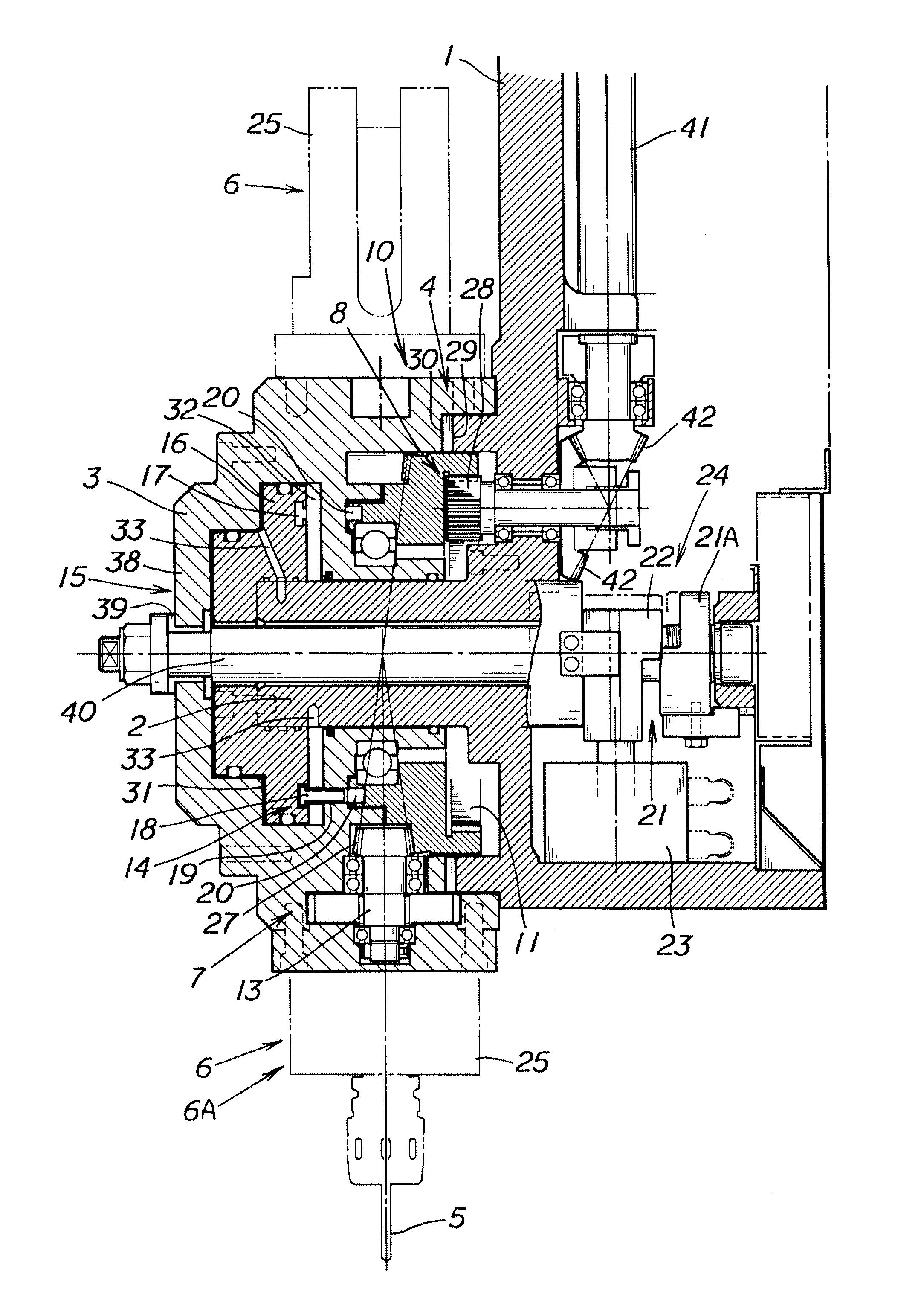
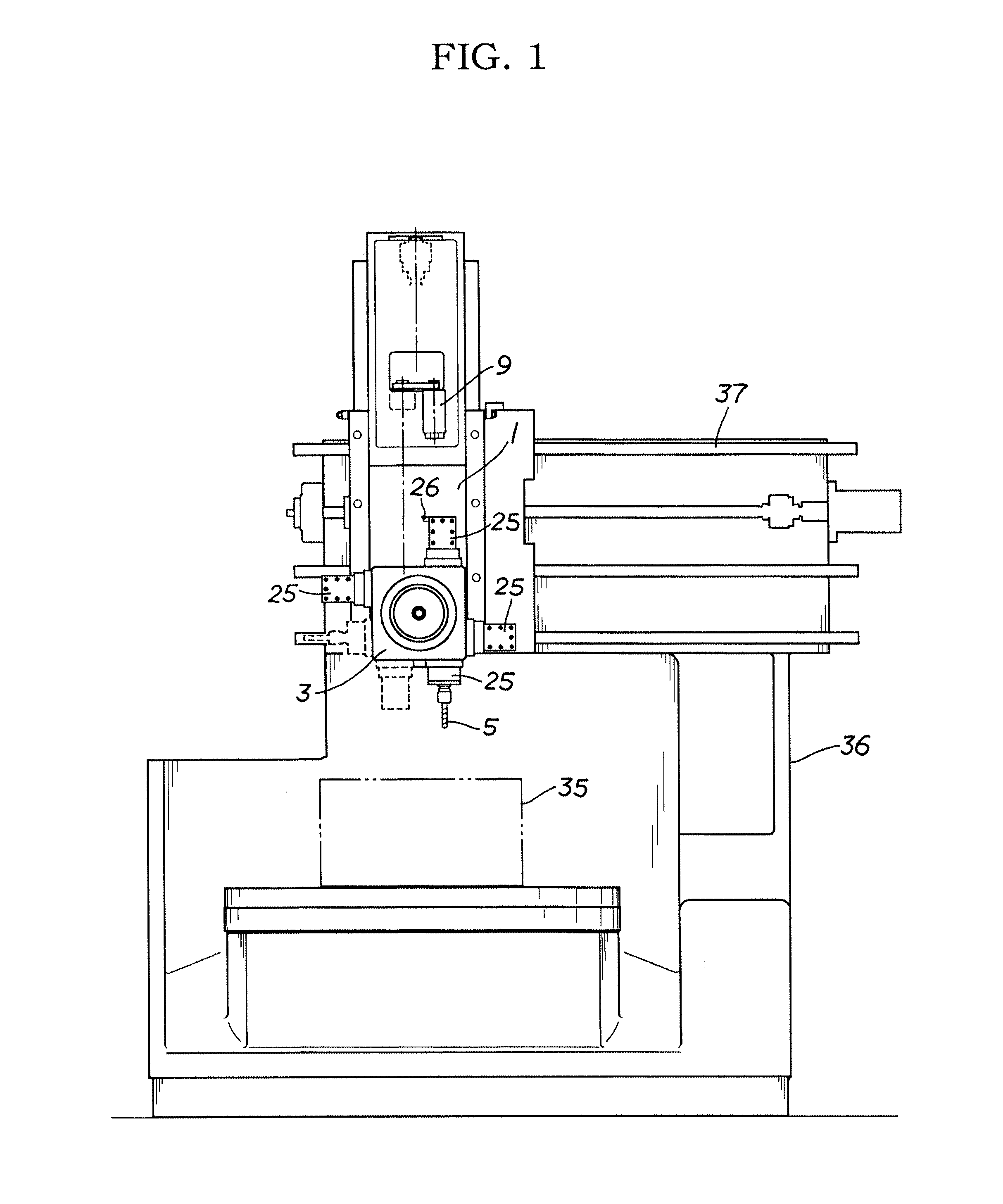
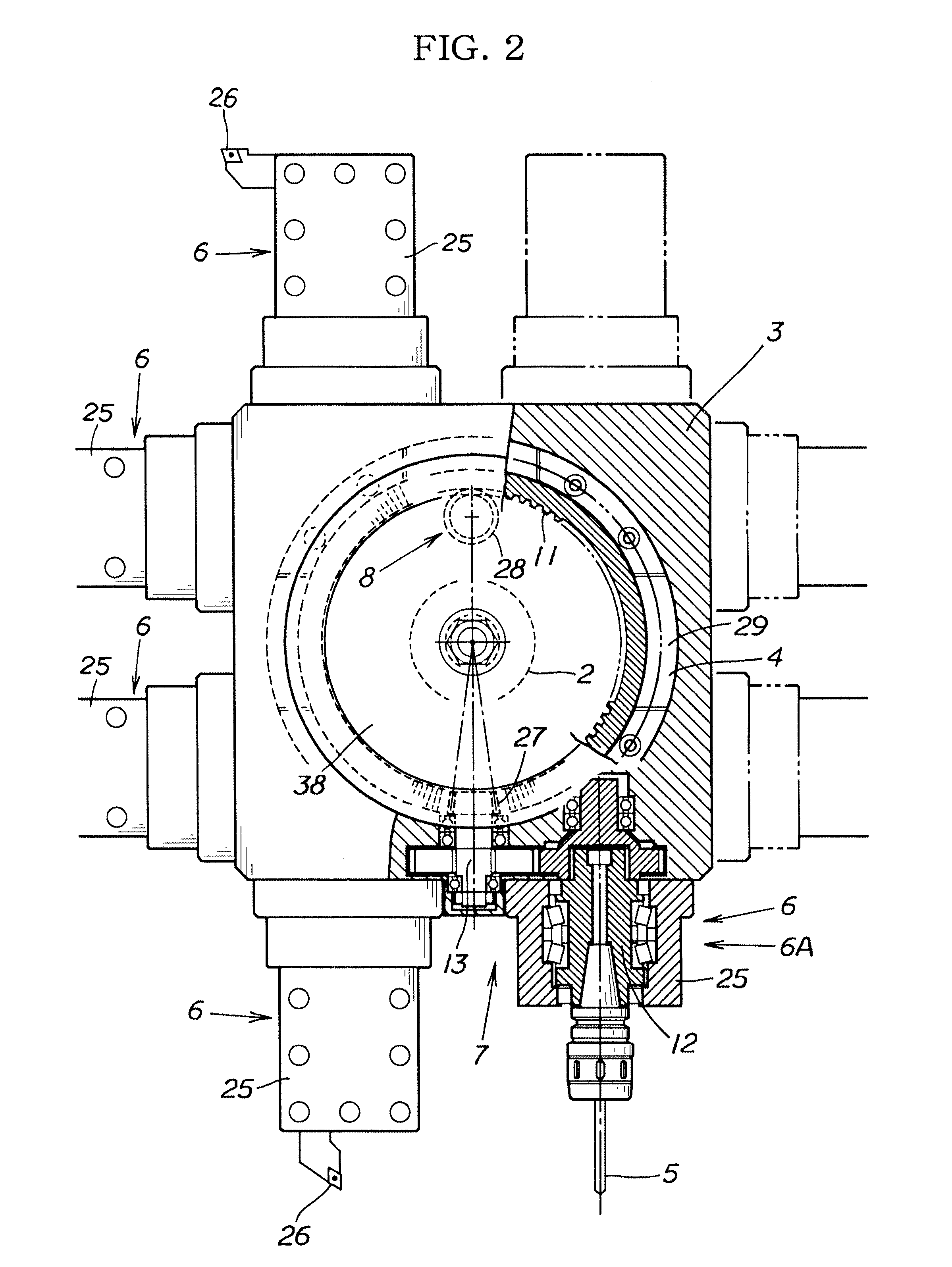
[0052]In the present example, the present invention is applied to an automatic swiveling turret device of a machine tool such as a vertical lathe, wherein tools are respectively provided to all sides of a turret 3 (a cutting tool 26 and a rotating tool 5 which can be replaced are provided to respective holders 25) which is moveably controlled in directions X, Y, and Z relative to a workpiece 35 via a column 36, a cross rail 37, and a turret head 1 as shown in FIG. 1, and if the turret 3 is square shaped, for example, the turret 3 is indexed in 90 degree increments relative to the turret head 1 to switch the tool being used.

[0053]Specifically, as has already been described in detail in the conventional example, the basic configuration of the turret device of the present example has a swivel shaft part 2 provided to the turret head 1, a turret 3 provided to the swivel shaft part 2 and capable of swive...


PUM

PropertyMeasurementUnit
Forceaaaaaaaaaa

Abstract

A composite processing machine with an automatic swiveling composite turret device. Transmitting and releasing of rotational force to a rotating tool is automatically switched between indexing and locked securing. Included is a clutch-action-coupled rotational force transmission / release switching mechanism (10). A common motor (9) is the drive source for a rotation drive mechanism (7) for transmitting rotational force to a rotating tool (5) and a swivel drive mechanism (8) for swiveling a turret (3). Transmission of rotational force of common motor (9) to rotation drive mechanism (7) is released when turret (3) is slid along swivel shaft part (2) to unlock clutch device (4) and enable turret (3) to swivel, and rotational force of common motor (9) is transmitted to rotating tool (5) when turret (3) is slid back to lock and secure clutch device (4) in an indexed position of turret (3).

Description

CROSS REFERENCE TO RELATED APPLICATIONS[0001]This application claims priority based on Japanese Patent Application No. 2012-170046 filed Jul. 31, 2012, the contents of all of which are incorporated herein by reference in their entirety.BACKGROUND OF THE INVENTION[0002]1. Field of the Invention[0003]The present invention relates to a composite processing machine having composite functions such as boring, which is also a machine tool comprising an automatic swiveling turret such as a large vertical lathe, for example.[0004]2. Description of the Related Art[0005]An automatic swiveling turret device, wherein a plurality of tools (tool holders) that are switched and used by swiveling are provided to a turret, and the turret is automatically swiveled relative to a turret head when the tool is switched or when the tool angle is changed, commonly has a configuration such as the following (referring to the drawings of the present example, the description appends the same symbols to the same ...

Claims


Application Information

Patent Timeline
IPC IPC(8): B23Q5/10B23Q16/10B23B29/32
CPCB23Q16/10B23B29/323B23Q5/10B23Q2220/002Y10T29/5155Y10T74/1494
Inventor SHIMIZU, TATSUONAKAMURA, TAKIOKABASAWA, KATSUNORIGOTO, AKIHIRO
Owner O M
Learn More