Center pillar outer and manufacturing method thereof

a technology of center pillar and manufacturing method, which is applied in the direction of superstructure subunits, vehicle components, transportation and packaging, etc., can solve the problems of serious fracture of center pillar, long time, and excessive increase of mold investment cost (initial investment cost) for mold, so as to optimize the side collision performance of the vehicle and prevent the fracture of the center pillar

Active Publication Date: 2016-04-19
KIA MOTORS CORP
View PDF18 Cites 6 Cited by
  • Summary
  • Abstract
  • Description
  • Claims
  • Application Information

AI Technical Summary

Benefits of technology

[0012]The present invention provides a center pillar outer and a manufacturing method thereof, in which a component is implemented to have a predetermined strength and rigidity for each portion so that it can guide deformation of a center pillar in the side collision of a vehicle and to prevent a fracture of the center pillar, thereby optimizing the side collision performance of the vehicle.
[0020]As described above, the center pillar outer according to the present invention have advantages as follows. First, the upper and lower end portions of the center pillar outer can be respectively implemented to have optimum strengths, to flexibly deal with physical requirements for each portion of a component. Accordingly, it is possible to prevent a fracture caused by a physical impact applied to each portion of the component in the side collision of the vehicle. Second, it is possible to reduce cost consumed in developing and manufacturing a mold, as compared with the conventional center pillar outer. Third, an overlapping structure is formed at a portion where a door hinge is mounted so that it can remove the conventional hinge bracket. Accordingly, it is possible to reduce weight and cost.

Problems solved by technology

When a protruding portion of a barrier with a rigid body collides with a lower portion of a center pillar of a side body in a vehicle side collision test, a serious fracture occurs in the center pillar, based on a barrier hitting portion (a section of the center pillar, where the protruding portion of the barrier directly hits the center pillar).
In this case, it takes a long time to develop the mold for hot stamping, and hence the mold investment cost (initial investment costs) for the mold is excessively increased.
Since the durability of the mold is weak, spare molds are additionally required.

Method used


Image

  • Center pillar outer and manufacturing method thereof
  • Center pillar outer and manufacturing method thereof
  • Center pillar outer and manufacturing method thereof

Examples


Embodiment Construction

[0030]Reference will now be made in detail to various embodiments of the present invention(s), examples of which are illustrated in the accompanying drawings and described below. While the invention(s) will be described in conjunction with exemplary embodiments, it will be understood that present description is not intended to limit the invention(s) to those exemplary embodiments. On the contrary, the invention(s) is / are intended to cover not only the exemplary embodiments, but also various alternatives, modifications, equivalents and other embodiments, which may be included within the spirit and scope of the invention as defined by the appended claims.

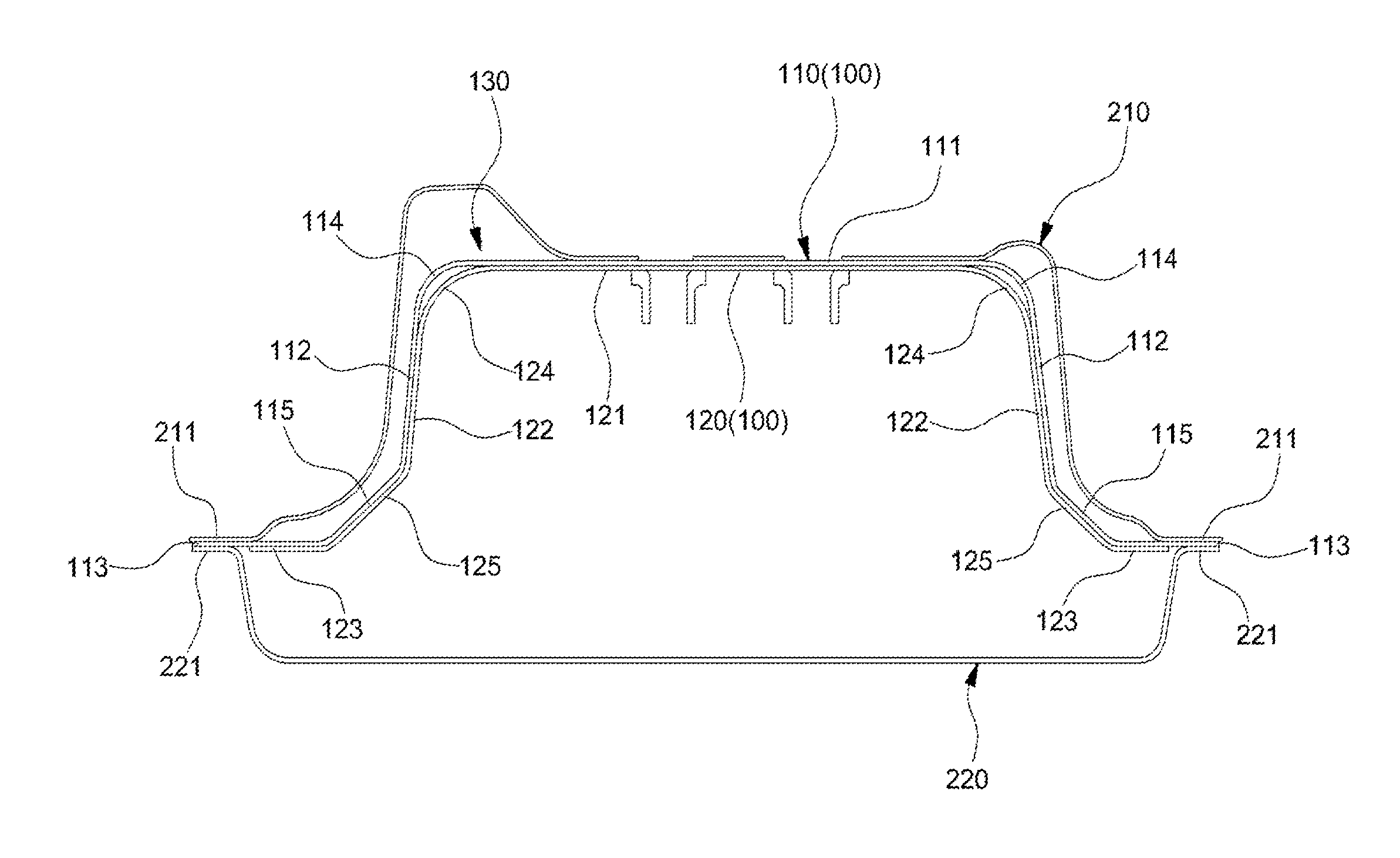
[0031]The present invention provides a panel component for improving side collision performance of a vehicle. In this case, the strength of the component for each portion is optimized so that it can guide deformation of the component in side collision of the vehicle and to prevent a fracture of the component.

[0032]Accordingly, in the ...


PUM

PropertyMeasurementUnit
strengthaaaaaaaaaa
temperatureaaaaaaaaaa
structureaaaaaaaaaa

Abstract

A center pillar outer, and a method of manufacturing a center pillar outer, may include an upper panel portion which forms an upper end portion of the center pillar outer, and a lower panel portion which forms a lower end portion of the center pillar outer. The upper and lower panel portions are molded using different methods. A lower end of the upper panel portion and an upper end of the lower panel portion are overlapped with each other, and the overlapping portions are coupled to each other, for example, through welding.

Description

CROSS-REFERENCE TO RELATED APPLICATION[0001]The present application claims priority of Korean Patent Application Number 10-2013-0158991 filed on Dec. 19, 2013, the entire contents of which application are incorporated herein for all purposes by this reference.BACKGROUND OF INVENTION[0002]1. Field of Invention[0003]The present invention relates to a center pillar outer and a manufacturing method thereof which can improve side collision performance of a vehicle.[0004]2. Description of Related Art[0005]When a protruding portion of a barrier with a rigid body collides with a lower portion of a center pillar of a side body in a vehicle side collision test, a serious fracture occurs in the center pillar, based on a barrier hitting portion (a section of the center pillar, where the protruding portion of the barrier directly hits the center pillar).[0006]In order to overcome such a serious fracture, a hot stamping method has been conventionally used in manufacturing of a panel component suc...

Claims


Application Information

Patent Timeline
Patent Type & Authority Patents(United States)
IPC IPC(8): B62D25/04B21D53/88B21D22/02
CPCB62D25/04B21D53/88B21D22/022Y10T29/49622
Inventor HEO, CHUL HEEOH, HEE DAE
Owner KIA MOTORS CORP
Why Eureka
Try Eureka