
Fluid dispensing device

a technology of liquid dispensing device and dispenser, which is applied in the direction of liquid transfer device, single-unit apparatus, drug composition, etc., can solve the problems of slow or unpredictable pump actuation, unreliable spray characteristics, and ineffective dispensing of medicament formulations

Active Publication Date: 2016-04-26
GLAXO GRP LTD
View PDF140 Cites 0 Cited by
  • Summary
  • Abstract
  • Description
  • Claims
  • Application Information

AI Technical Summary

Benefits of technology

[0058]In one particular aspect, the force modifying means additionally comprises a stop feature, which acts to stop force being applied to the container once either a particular maximum force is reached or more typically, once the container has been moved a particular distance. In one aspect, the stop functions to prevent excess force being applied to the compression pump.
[0060]The medicament particles comprise an active medicament, which may be selected from, for example, analgesics, e.g. codeine, dihydromorphine, ergotamine, fentanyl or morphine; anginal preparations, e.g., diltiazem; antiallergics, e.g., cromoglycate (eg as the sodium salt), ketotifen or nedocromil (eg as the sodium salt); antiinfectives e.g., cephalosporins, penicillins, streptomycin, sulphonamides, tetracyclines and pentamidine; antihistamines, e.g., methapyrilene; anti-inflammatories, e.g., beclomethasone (eg as the dipropionate ester), fluticasone (eg as the propionate ester), flunisolide, budesonide, rofleponide, mometasone (eg as the furoate ester), ciclesonide, triamcinolone (eg as the acetonide), 6α,9α-difluoro-11β-hydroxy-16α-methyl-3-oxo-17α-propionyloxy-androsta-1,4-diene-17β-carbothioic acid S-(2-oxo-tetrahydro-furan-3-yl) ester or 6α,9α-Difluoro-17α-[(2-furanylcarbonyl)oxy]-11β-hydroxy-16α-methyl-3-oxo-androsta-1,4-diene-17β-carbothioic acid S-fluoromethyl ester; antitussives, e.g., noscapine; bronchodilators, e.g., albuterol (eg as free base or sulphate), salmeterol (eg as xinafoate), ephedrine, adrenaline, fenoterol (eg as hydrobromide), formoterol (eg as fumarate), isoprenaline, metaproterenol, phenylephrine, phenylpropanolamine, pirbuterol (eg as acetate), reproterol (eg as hydrochloride), rimiterol, terbutaline (eg as sulphate), isoetharine, tulobuterol or 4-hydroxy-7-[2-[[2-[[3-(2-phenylethoxy)propyl]sulfonyl]ethyl]amino]ethyl-2(3H)-benzothiazolone; PDE4 inhibitors eg cilomilast or roflumilast; leukotriene antagonists eg montelukast, pranlukast and zafirlukast; [adenosine 2a agonists, eg 2R,3R,4S,5R)-2-[6-Amino-2-(1S-hydroxymethyl-2-phenyl-ethylamino)-purin-9-yl]-5-(2-ethyl-2H-tetrazol-5-yl)-tetrahydro-furan-3,4-diol (e.g. as maleate)]*; [α4 integrin inhibitors eg (2S)-3-[4-({[4-(aminocarbonyl)-1-piperidinyl]carbonyl}oxy)phenyl]-2-[((2S)-4-methyl-2-{[2-(2-methylphenoxy) acetyl]amino}pentanoyl)amino]propanoic acid (e.g as free acid or potassium salt)]*, diuretics, e.g., amiloride; anticholinergics, e.g., ipratropium (eg as bromide), tiotropium, atropine or oxitropium; hormones, e.g., cortisone, hydrocortisone or prednisolone; xanthines, e.g., aminophylline, choline theophyllinate, lysine theophyllinate or theophylline; therapeutic proteins and peptides, e.g., insulin or glucagons. It will be clear to a person skilled in the art that, where appropriate, the medicaments may be used in the form of salts, (e.g., as alkali metal or amine salts or as acid addition salts) or as esters (e.g., lower alkyl esters) or as solvates (e.g., hydrates) to optimise the activity and / or stability of the medicament and / or to minimise the solubility of the medicament in the propellant.
[0079]Suitable isotonicity adjusting agents act such as to achieve isotonicity with body fluids (e.g. fluids of the nasal cavity), resulting in reduced levels of irritancy associated with many nasal formulations. Examples of suitable isotonicity adjusting agents are sodium chloride, dextrose and calcium chloride.
[0108]Suitably, a dispensing orifice of the nozzle is provided with a reversible stopper. The stopper acts such as to prevent drain back of delivered fluid from the nozzle (in particular, from the area at the tip of the nozzle and generally adjacent to the dispensing orifice).
[0109]Suitably, the stopper is reversibly mountable to the nozzle (e.g. at the tip) to enable reversible sealing of the dispensing orifice thereof. In use, such sealing acts such as to minimise drain back of fluid from the dispensing orifice through the interior of the nozzle.
[0151]Suitably, the co-operating guide members prevent rotation of the dispensing member about the axis.

Problems solved by technology

It is a problem with such a prior art sprays that if the actuator is moved in a slow or unpredictable manner a strong and well-defined spray may not be produced and so the medicament formulation may not be effectively dispensed.
This problem is particularly significant where an actuator (e.g. a lever) acts on a pump mechanism such as to pump the fluid to be sprayed from a container.
In this case, slow or unpredictable actuation results in a slow or unpredictable actuation of the pump and hence, unreliable spray characteristics.

Method used


Image

  • Fluid dispensing device
  • Fluid dispensing device
  • Fluid dispensing device

Examples


second embodiment

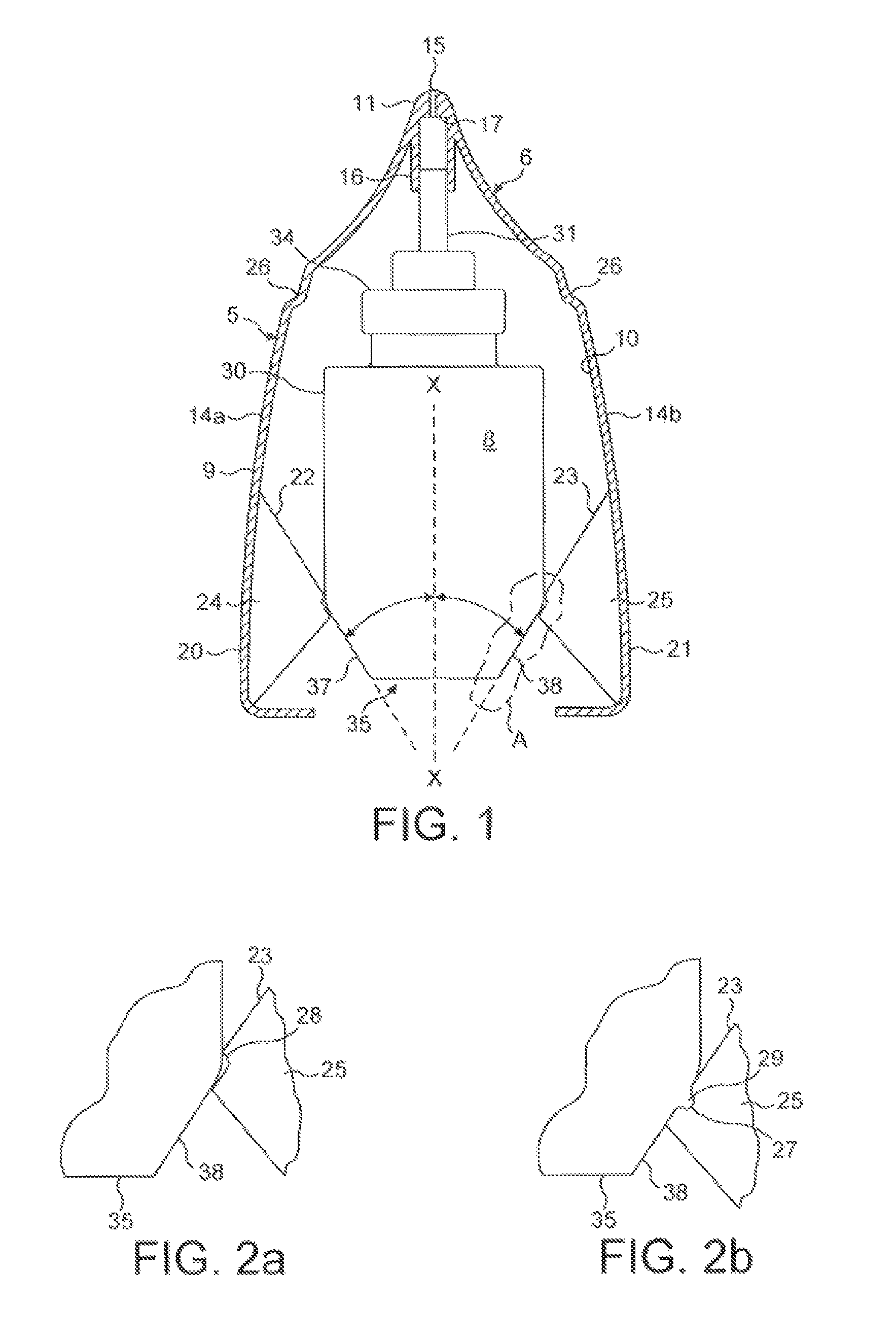
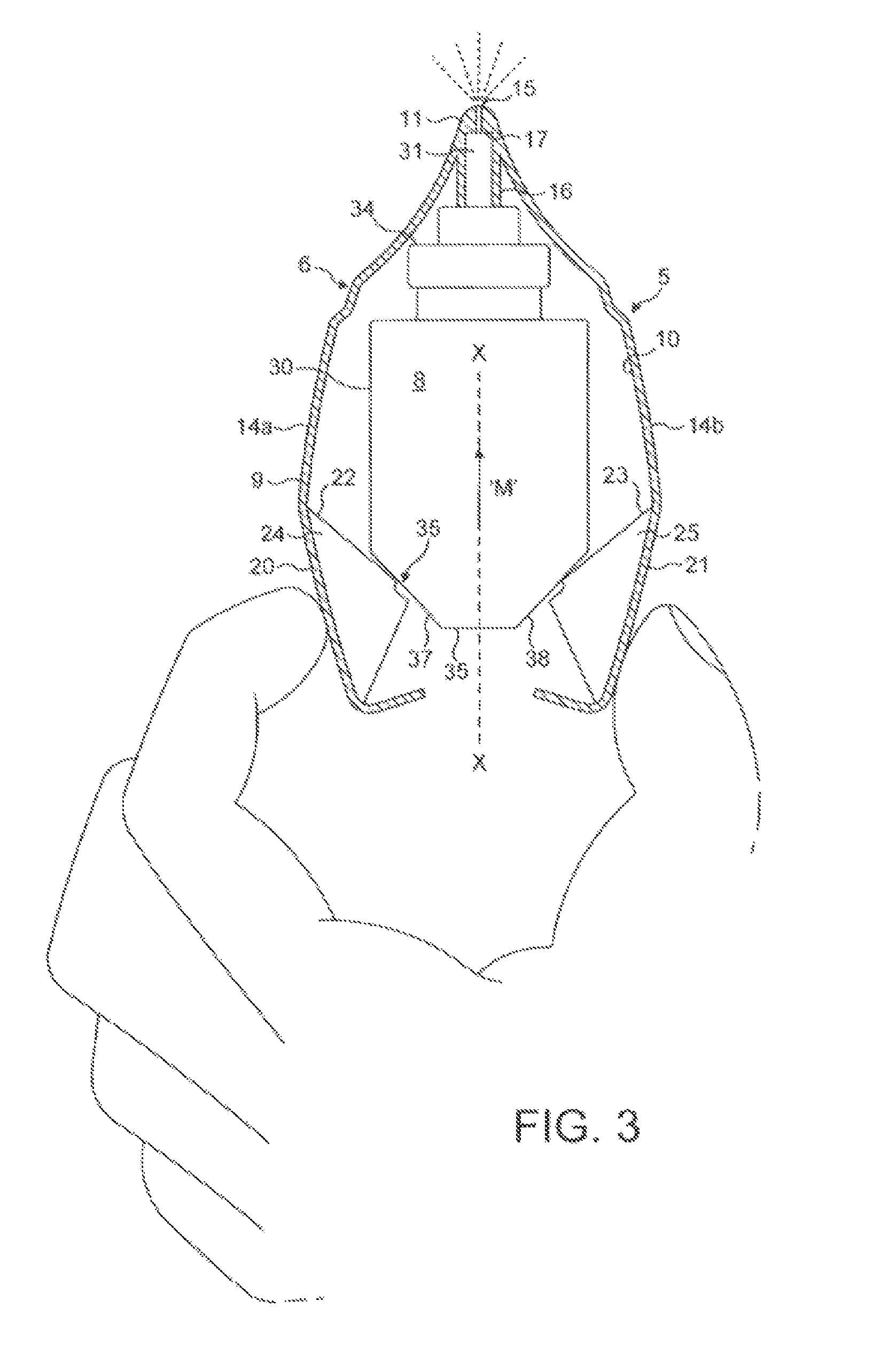
[0237]The primary difference between the fluid dispensing means shown in FIGS. 1 to 3 and that shown in FIGS. 4 and 5 is that the fluid dispensing device 5 in FIGS. 4 and 5 uses pre-load means in which the pre-load means 39, 40 is interposed between the housing 9 and the container 30.

[0238]The pre-load means comprises of two detents 39, 40 formed on the housing 9 for engagement with part of the container 30. The two detents 39, 40 are disengageable from the container 30 when the pre-determined force is applied to the finger operable means 20, 21 so as to allow the compression pump to be actuated.

[0239]Each of the detents is in the form of an arm 39, which extends downwardly from the housing 9 for engagement with a corner of the neck 34 of the container 30. A free end of each arm 39 has a step 40 formed therein, which prior to actuation is in abutting contact with the neck 34 of the container 30.

[0240]Operation of the fluid dispensing device is as follows.

[0241]From the position show...

third embodiment

[0247]The primary difference between the fluid dispensing means shown in FIGS. 1 to 3 and that shown in FIGS. 6 to 8 is that the fluid dispensing device 5 in FIGS. 6 to 8 uses pre-load means in which the pre-load means 41, 42, 43 is interposed between the container 30 and the discharge tube 31.

[0248]This embodiment has the advantage that it can be used irrespective of the mechanism used to actuate the pump.

[0249]The pre-load means comprises of a step 41 formed on the discharge tube 31 and two latching members in the form of arms 42 attached by a collar 43 to the neck 34 of the container 30. The step 41 is formed by a rib 44 extending circumferentially around the discharge tube 31 and positioned such that when the pump is actuated the rib 44 does not prevent travel of the discharge tube 31 into the container 30.

[0250]The arrangement is such that, when the pre-determined force is applied to the finger operable means in the form of the levers 20, 21, the latching members or arms 42 are...

fourth embodiment

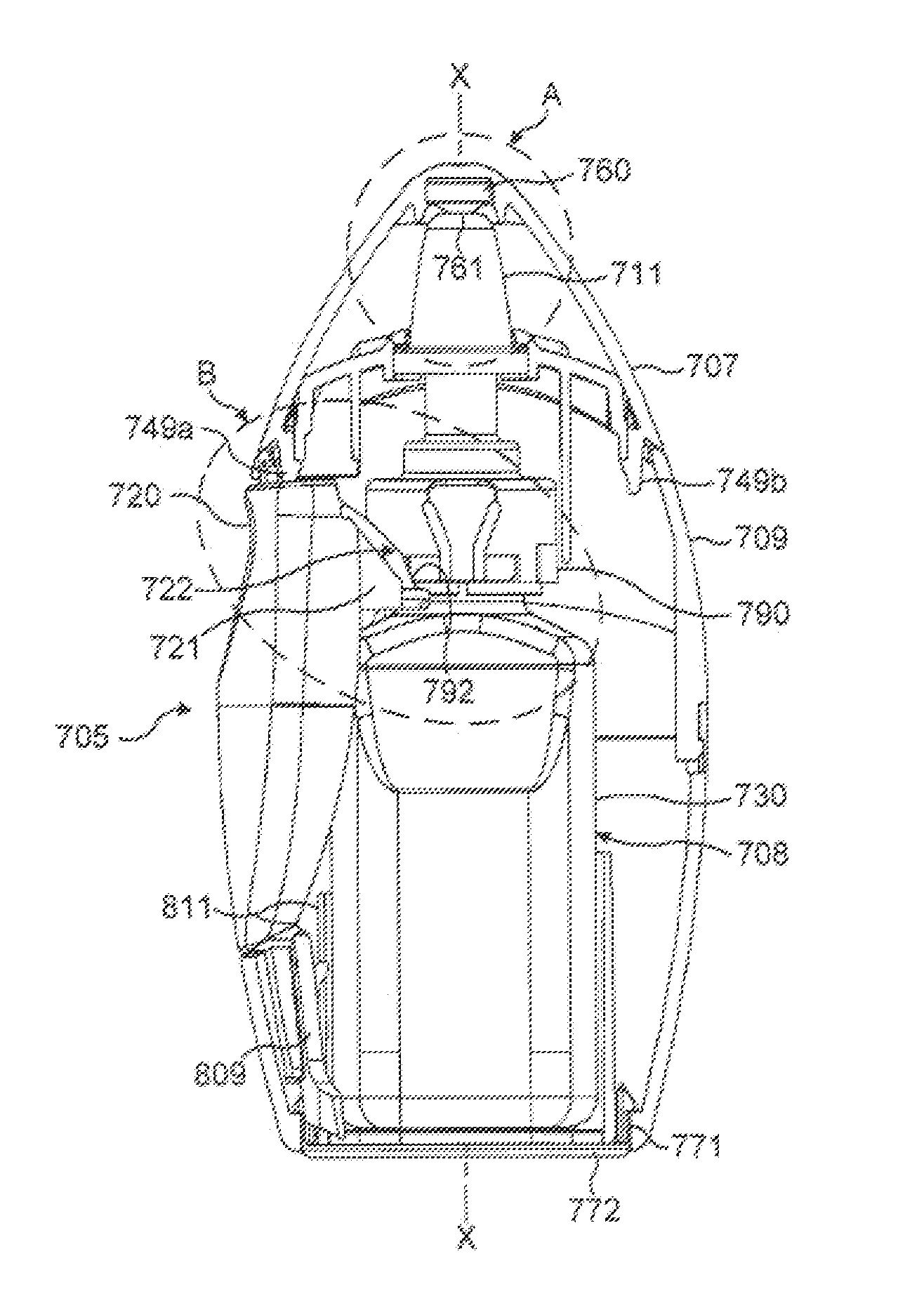
[0286]The fluid dispensing device 165 is fitted with a pre-load means in which the pre-load means 150, 152, 153 is interposed between the housing 109 and the lever 170.

[0287]The pre-load means comprises of a detent in the form of a tooth 150 formed on the housing 109 for engagement with the lever 170. The tooth 150 is formed at the end of an arm 152 formed as an integral part of the housing 109 and the lever 170 has a complementary rib 153 formed thereon for engagement with the tooth 150.

[0288]The detent or tooth 150 is disengageable from the rib 153 on the lever 170 when a pre-determined force is applied to the lever 170 so as to allow the compression pump to be actuated.

[0289]In more detail the fluid dispensing device 165 comprises of a body structure including the housing 109, the nozzle 111 extending out from an upper end of the housing 109 for insertion into a body cavity and a fluid discharge device 108 moveably housed within the housing 109.

[0290]The fluid discharge device 10...


PUM


Abstract

A fluid dispensing device for dispensing a fluid form medicament formulation having a viscosity of from 10 to 2000 mPa·s, is disclosed having a housing and a fluid discharge device. The fluid discharge device is arranged to be actuated by one or more levers, so as to apply a force to the fluid discharge device which is used to move a container forming part of the fluid discharge device, along a longitudinal axis of the fluid discharge device to cause actuation of a pump forming. A pre-load mechanism prevents actuation of the pump until a pre-determined force is applied to each lever of sufficient magnitude to guarantee the production of a well-developed, efficient spray from the fluid dispensing device.

Description

CROSS-REFERENCE TO RELATED APPLICATIONS[0001]The present application is a Continuation of U.S. patent application Ser. No. 10 / 577,977, filed on May 3, 2006, which issued as U.S. Pat. No. 8,752,543 on Jun. 17, 2014; which was a US National Phase application filed pursuant to 35 U.S.C. §371 of International Patent Application No. PCT / GB2004 / 004626 filed Nov. 2, 2004; which claims priority from Application No. 0325629.4 filed on Nov. 3, 2003; Application No. 0405477.1 filed on 11 Mar. 2004; and Application No. 0420539.9 filed on Sep. 17, 2004, each filed in the United Kingdom; and each of which are incorporated herein by reference.BACKGROUND OF THE INVENTION[0002]The present invention relates to a medicament dispenser and in particular to a fluid dispensing device for use as a nasal inhaler.[0003]It is known to provide a medicament dispenser, in which fluid spray is dispensed via a nozzle or orifice upon the application of a force by a user to an actuation lever or button. Such devices...

Claims


Application Information

Patent Timeline
Patent Type & Authority Patents(United States)
IPC IPC(8): A61M15/00A61M15/08B65D83/38B65D83/20B65D83/16B05B11/00B67D7/84B65D83/14
CPCA61M15/0001A61M15/009A61M15/08B05B11/3052B05B11/3056B05B11/3059B65D83/386B05B11/0037B65D83/16B65D83/201B05B11/0038A61P11/02A61P11/06A61P29/00B05B11/1056B05B11/1059B05B11/1052
Inventor DAVIES, MICHAEL BIRSHAHEDLEY, MARK GRAHAMGODFREY, JAMES WILLIAM
Owner GLAXO GRP LTD
Learn More