Installation frame for accommodating a device in an installation opening

a technology for installing openings and devices, applied in the field of installation frames, can solve the problems of time-consuming installation, inconvenient installation, and disadvantageous rears

Inactive Publication Date: 2016-04-26
ROBERT BOSCH GMBH
View PDF6 Cites 0 Cited by
  • Summary
  • Abstract
  • Description
  • Claims
  • Application Information

AI Technical Summary

Benefits of technology

[0006]An object of the present invention is therefore to provide an installation frame which eliminates the aforementioned disadvantages of the known approaches.
[0007]Example embodiments of the present invention may have the advantage that an installation frame for accommodating a device may be easily and securely attached within the installation opening. The approach described herein makes do with little assembly complexity. Compared to previous approaches, an example installation frame according to the present invention may be installed without much specialized knowledge or specialized skill and within a short period of time, and it is thus suitable, in particular, for assembly line production in an automobile manufacturing plant. Compared to previous approaches, the attachment of the installation frame is more stable; in particular, it is insensitive to mechanical shocks such as hits or impact. In particular, the stability of the installation is also largely independent of the quality of the fitter's work.

Problems solved by technology

In this attachment method, the fact that a secure connection is not provided in the event of an impact from the rear has turned out to be disadvantageous.
The installation is furthermore time-consuming, due to the necessary bending of the latching tabs or latching means.
This, in turn, presents an obstacle to assembly during vehicle manufacture on an assembly line.
In particular, the stability of the installation is also largely independent of the quality of the fitter's work.

Method used


Image

  • Installation frame for accommodating a device in an installation opening
  • Installation frame for accommodating a device in an installation opening
  • Installation frame for accommodating a device in an installation opening

Examples


Embodiment Construction

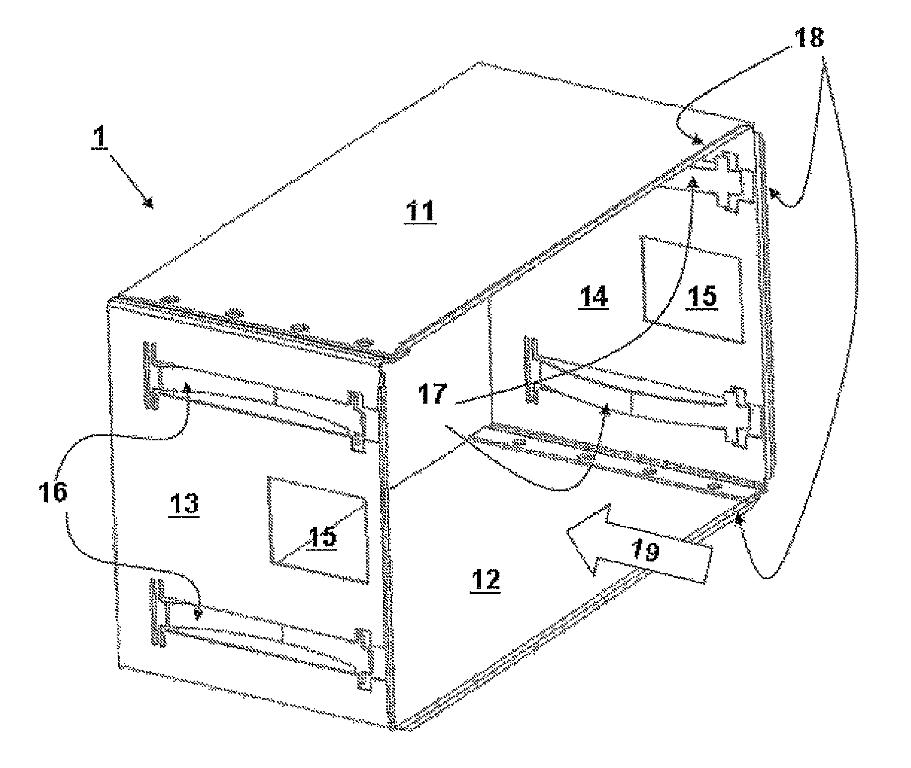
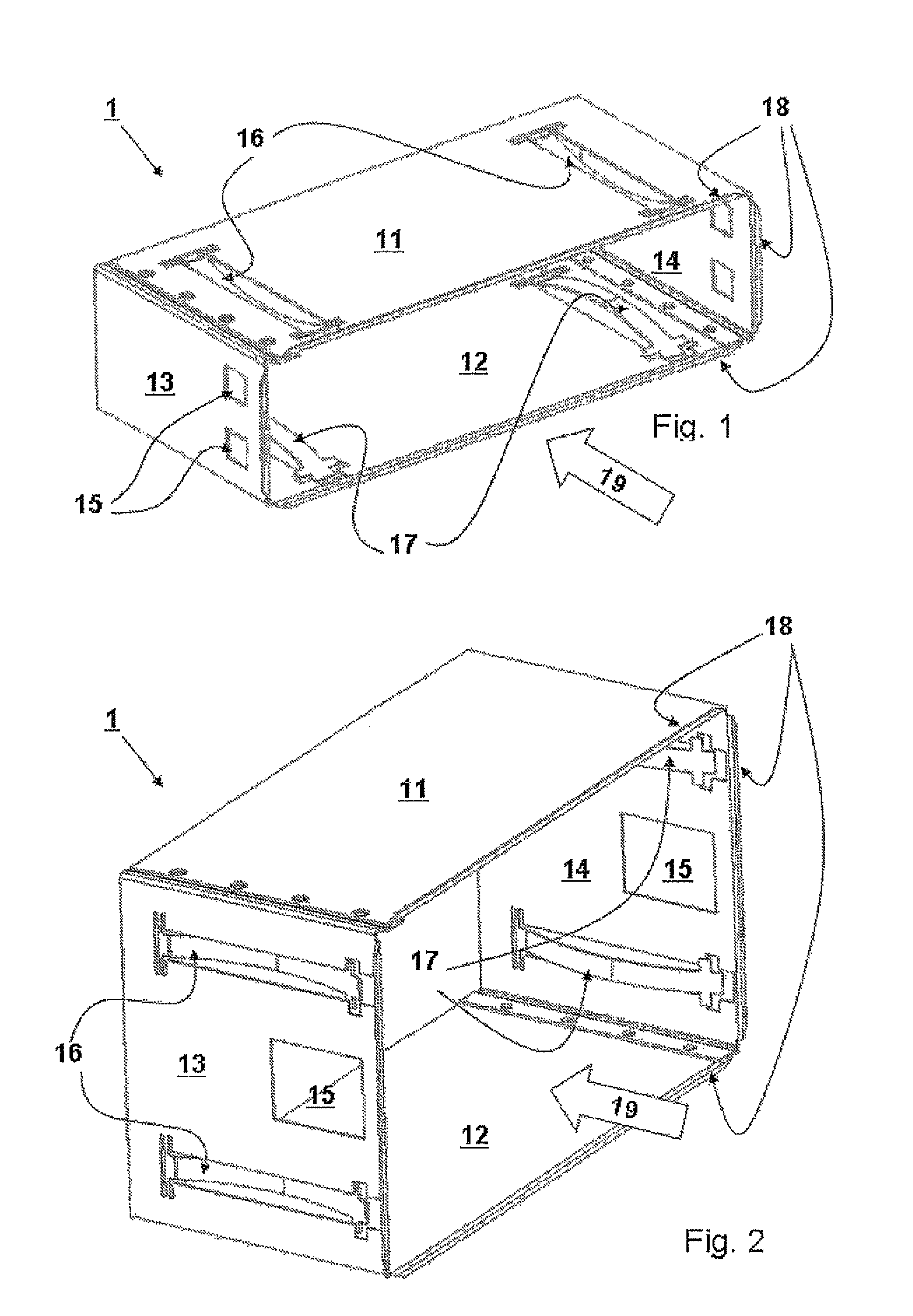
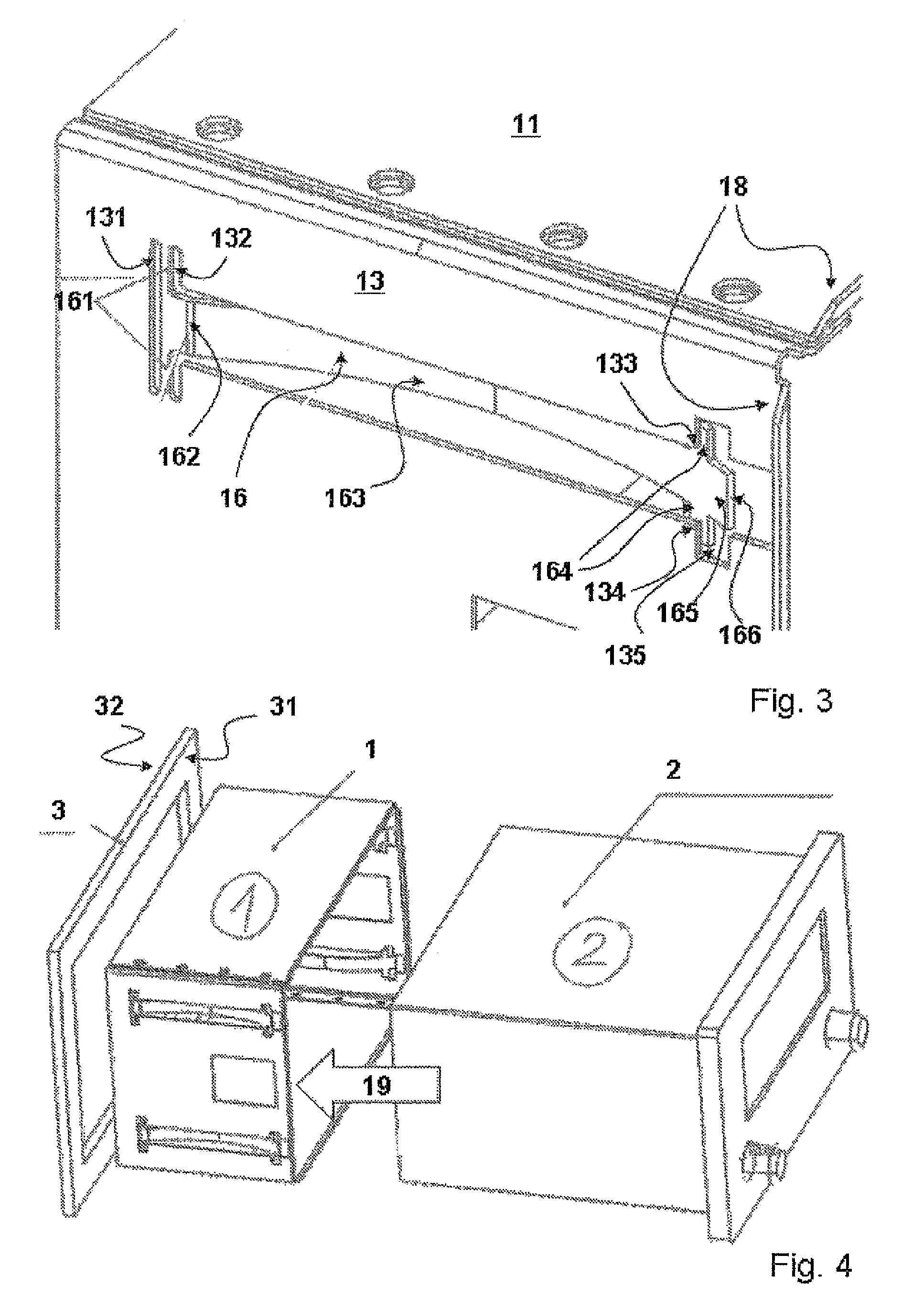
[0016]FIG. 1 shows an installation frame 1 according to the present invention by way of example. This installation frame 1 has a cover 11, a base 12 as well as a left side wall 13 and a right side wall 14. Cover 11, base 12 and both side walls 13 and 14 enclose a largely cuboid space which is used to accommodate a device, for example a car radio or navigation unit 2 (see FIG. 4). To accommodate device 2, installation frame 1 has at least one opening on the front, into which device 2 may be inserted along arrow 19. Installation frame 1 is also preferably open at the back, for example to be able to easily install connecting lines for device 2.

[0017]Installation frame 1 has openings 15 in its side walls 13 and 14. These openings are used to attach device 2 in a conventional manner, for example as described in German Patent No. DE 29 03 176 C2. For this purpose, device 2 has appropriate latching means on the side walls of its housing which engage with openings 15 in the end position of ...


PUM

PropertyMeasurementUnit
heightaaaaaaaaaa
areaaaaaaaaaaa
elasticaaaaaaaaaa

Abstract

An installation frame for accommodating a device in a predefined installation opening is described. The installation frame has wall sections which enclose a largely cuboid cavity which is open at least on the front for accommodating the device, front edges of at least a portion of the wall sections forming flange-like outwardly projecting edge sections for resting against a front edge of the installation opening. The installation frame also has a latching arrangement which project to the outside from at least a portion of the wall sections and engage with the back of the installation opening, wherein the latching means have at least approximately arc-shaped sections which extend into the cavity and furthermore have an end section which projects to the outside through the wall sections for engaging with the installation opening in such a way that the arc-shaped sections are flattened when the device is inserted into the cavity and consequently are elongated in the direction of the back of the installation opening so that the installation opening is clamped between the front edge sections and the latching means of the installation frame. The installation frame may be easily, quickly and securely attached within the installation opening.

Description

FIELD OF THE INVENTION[0001]The present invention is directed to an installation frame.BACKGROUND INFORMATION[0002]An installation system for installing an auxiliary device in a predefined installation opening, in particular a standardized installation shaft in a motor vehicle, is described in German Patent No. DE 29 03 176 C2. This installation system includes an installation frame for accommodating and attaching the auxiliary device. The installation frame has wall sections which enclose a largely cuboid cavity which is open at least on the front for accommodating the auxiliary device, front edges of at least a portion of the wall sections forming flange-like outwardly projecting edge sections for resting against a front edge of an installation opening. Furthermore, a latching arrangement, which projects to the outside after being deformed from the wall sections and which engages with the back of the installation opening, is molded onto the wall sections. The installation frame is...

Claims


Application Information

Patent Timeline
Patent Type & Authority Patents(United States)
IPC IPC(8): H05K9/00G06F1/18B60R11/02B60R11/00
CPCB60R11/0211H05K9/0016B60R2011/0075B60R2011/0078Y10T29/53961G06F1/184
Inventor ANDERS, BERNWARD
Owner ROBERT BOSCH GMBH
Why Eureka
Try Eureka