Injection valve having a flow limiter

a technology of injection valve and flow limiter, which is applied in the direction of valve arrangement, fuel injection apparatus, charge feed system, etc., can solve the problems of increasing the length of the needle stroke, the change of application, and the increase of the flow volume, so as to reduce the flow cross section, increase the needle stroke length, and simple and economical design

Inactive Publication Date: 2016-04-26
ROBERT BOSCH GMBH
View PDF13 Cites 1 Cited by
  • Summary
  • Abstract
  • Description
  • Claims
  • Application Information

AI Technical Summary

Benefits of technology

[0003]The injection valve according to the present invention for injecting fuel has, in contrast, the advantage that a flow volume can be kept constant over the service life of the valve. Two throttling points for the fuel path are moreover produced when the valve is open, specifically at a valve positioning member lifted from the valve seat and at a flow limiting element. Even if increased wear on components, which would lead to an increase in needle stroke length, occurs during the utilization period of the injection valve, it is thus possible according to the present invention, as a result of the disposition of the flow limiting element on the valve positioning member, to provide compensation by reducing a flow cross section between the flow limiting element and a step provided in an inflow orifice. The valve according to the present invention has a very simple and economical design.
[0004]Particularly preferably, the valve is an outward-opening injection valve. The result is that, in particular, a risk of carbon deposition on the valve can be appreciably reduced, and compensation for wear can nevertheless be ensured by way of the flow limiting element according to the present invention.
[0006]Particularly preferably, the tapering surface of the flow limiting element is a conical surface. This can be manufactured very simply and cost-effectively. In addition, it is thereby possible in particular to compensate for a substantially constant wear by way of the flow limiting element.
[0007]According to a preferred alternative embodiment, the tapering surface is of convex or concave embodiment. This makes it possible to take into account, depending on the application, wear that increases differently over the service life.

Problems solved by technology

On the other hand, with outward-opening valves the stop surfaces of the magnet armature can change with increasing wear, so that a needle stroke length can increase over time.
This results in an increase in the flow volume, however, which can bring about a change in application.

Method used


Image

  • Injection valve having a flow limiter
  • Injection valve having a flow limiter
  • Injection valve having a flow limiter

Examples


Embodiment Construction

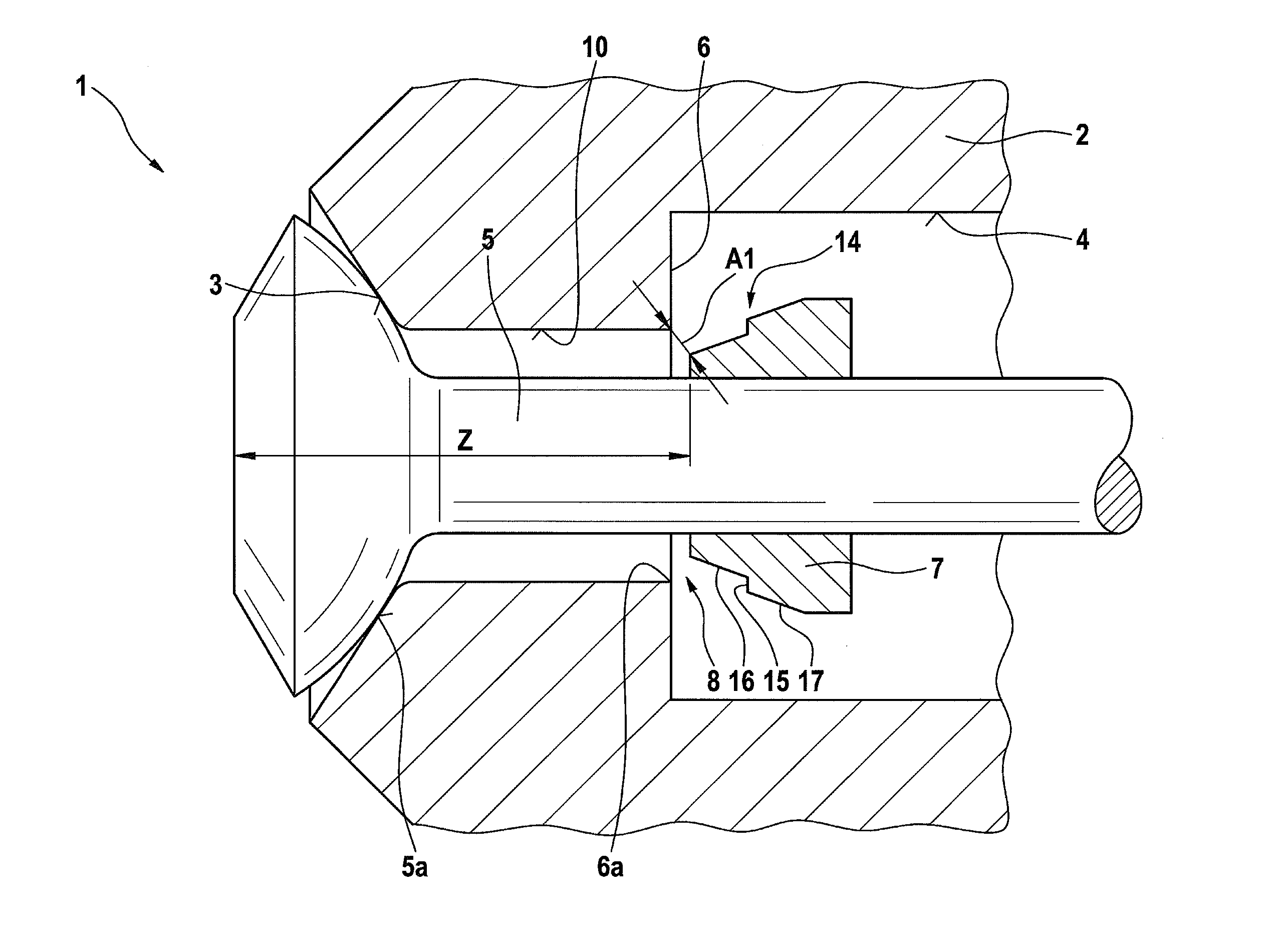
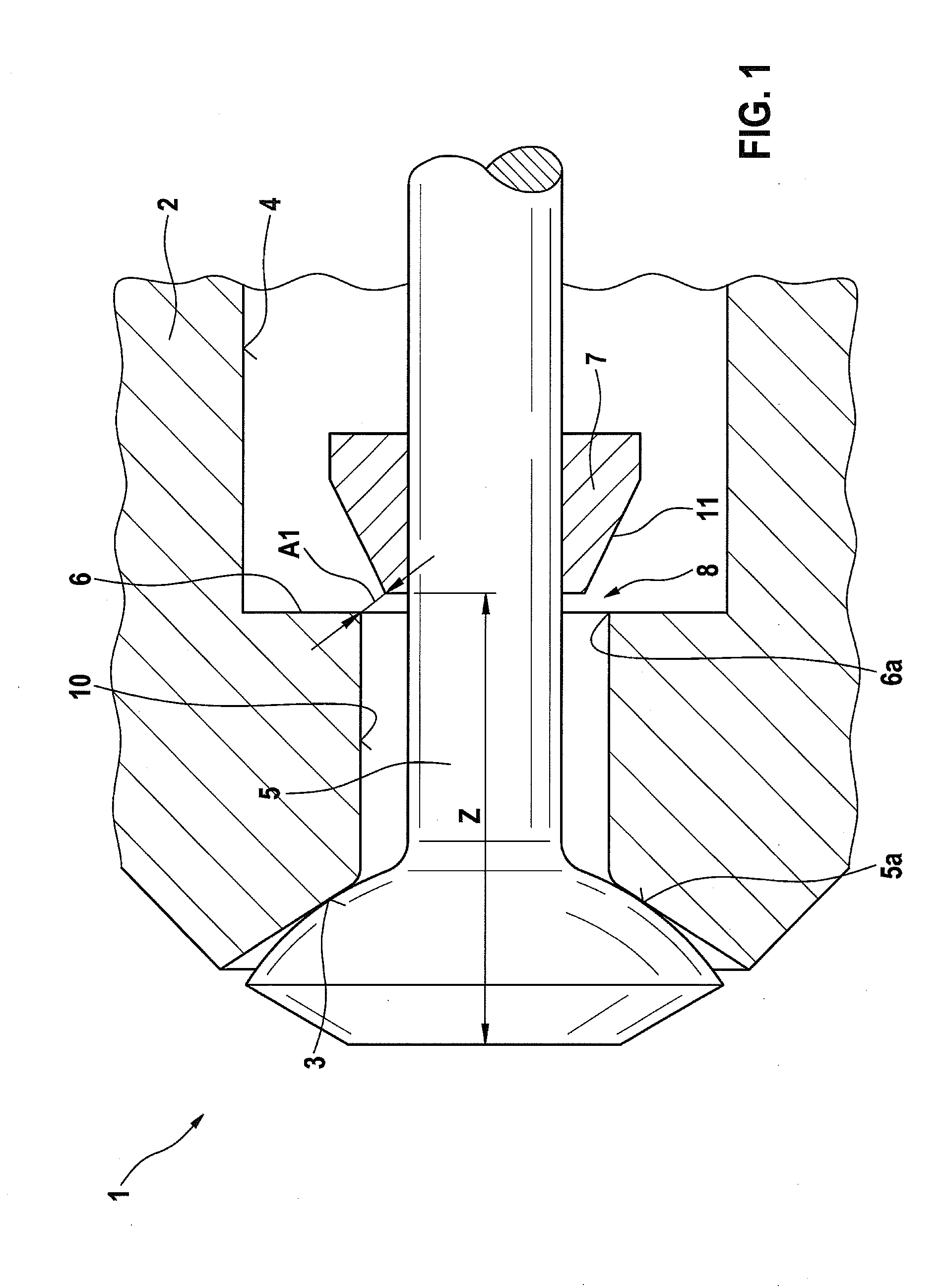
[0016]An injection valve 1 according to a first preferred exemplifying embodiment will be described in detail below with reference to FIGS. 1 and 2.

[0017]As is evident from FIG. 1, injection valve 1 encompasses a valve carrier 2 on which a step-shaped inflow orifice 4 is provided. Inflow orifice 4 encompasses a step 6 as well as a flow region 10 of constant diameter located between step 6 and a valve seat 3 in the flow direction (see FIG. 2, arrow B). A valve needle constituting a valve positioning member 5 seals against valve seat 3 in known fashion. As is further evident from FIG. 1, a flow limiting element 7 is mounted on the valve needle. As is evident from the closed state of the injection valve shown in FIG. 1, an annular flow area A1 is defined, between flow limiting element 7 and an annularly peripheral annular edge 6a of step 6, at a flow gap 8. Flow limiting element 7 has a region 11 tapering conically in flow direction B.

[0018]As is evident from FIG. 1, this results in a ...


PUM


Abstract

A valve for injecting fuel includes a valve carrier having a valve seat and an inflow orifice, a valve positioning member, and a flow limiting element that is disposed on the valve positioning member. The inflow orifice includes a step having a peripheral annular edge, and the flow limiting element is disposed on the valve positioning member in such a way that when the valve is opened, a flow area between the annular edge and the flow limiting element is reduced from a first flow area to a second flow area.

Description

FIELD OF THE INVENTION[0001]The present invention relates to an injection valve for injecting fuel, having a flow limiting element.BACKGROUND INFORMATION[0002]Injection valves that are embodied as multi-orifice valves having a magnetic drive, or as an outward-opening injection valve having a piezo drive, are known from the existing art. Whereas on the one hand the magnetically driven injection valves can be manufactured relatively economically, the piezo injection valves are substantially more robust with regard to carbon deposition because of the outward-opening valve positioning members. In magnetic injection valves a stop that minimizes variation in a fuel flow in the new condition is often provided. In addition, there must be no negative effects on vehicle operation due to the influence of inflow effects of the stop. On the other hand, with outward-opening valves the stop surfaces of the magnet armature can change with increasing wear, so that a needle stroke length can increase...

Claims


Application Information

Patent Timeline
Patent Type & Authority Patents(United States)
IPC IPC(8): F16K1/42F02M61/18F02M61/08F16K1/38
CPCF02M61/08F02M61/18F16K1/42F16K1/385
Inventor VORBACH, MARCO
Owner ROBERT BOSCH GMBH
Why Eureka
Try Eureka