Resonant device with piezoresistive detection and with a resonator connected elastically to the support of the device, and method for manufacturing the device

a piezoresistive detection and resonant technology, applied in the direction of material strength analysis using repeated/pulsating forces, material strength analysis using sonic/ultrasonic/infrasonic waves, etc., can solve the problems of noise coming to the frequency of interest, resonator is no longer stable, and resonator becomes difficult to control, so as to reduce the loss of strain in the anchoring. , the effect of high vibration amplitud

Active Publication Date: 2016-04-26
COMMISSARIAT A LENERGIE ATOMIQUE ET AUX ENERGIES ALTERNATIVES
View PDF10 Cites 3 Cited by
  • Summary
  • Abstract
  • Description
  • Claims
  • Application Information

AI Technical Summary

Benefits of technology

[0049]In this device the resonator may have a high vibration amplitude, i.e. it may have a vibration regime which remains linear across a very wide field of amplitudes, whilst permitting use of symmetrical boundary conditions, i.e. conditions which are identical at both ends of the resonator, and whilst minimising loss of strain in an anchoring.
[0051]In addition, in a preferred embodiment of the device, spectral noise density Sx, and therefore the output noise, are low; in other words, the device's transduction gain is high.
[0060]In the device forming the object of the invention, conversely, in addition to one or more strain gauges, at least one flexurally elastic element is used, through which the resonator is anchored to the support. This element enables the threshold at which the non-linearities appear to be raised. Such a flexurally elastic element allows the resonator to have greater freedom of movement: for example, when the latter is beam-shaped, the element gives it a freedom of movement along its axis (longitudinal direction) and rotational freedom of movement (around an axis perpendicular to the plane of the figures of the present application).

Problems solved by technology

In other words, in this non-linear regime, the resonator is no longer stable.
The resonator then becomes difficult to control.
Indeed, noise (at low or high frequency) is mixed by the non-linear component of the resonator, and brings noise to the frequency of interest.
Not only is the system consequently not stable in an open loop, but in addition the signal-to-noise ratio is degraded.
Thus, the more the beam is subjected to bending at large amplitudes, the greater its stiffness becomes.
This poses a problem.
In addition, one of the sources of damping of the movement of the beam results from this loss of strain in the anchoring; the quality factor of the resonant device in question in document [4] is thereby degraded.
But the limit of the vibration amplitude, which is determined by the appearance of the non-linear behaviour (see above), may prevent the desired performance from being attained.

Method used


Image

  • Resonant device with piezoresistive detection and with a resonator connected elastically to the support of the device, and method for manufacturing the device
  • Resonant device with piezoresistive detection and with a resonator connected elastically to the support of the device, and method for manufacturing the device
  • Resonant device with piezoresistive detection and with a resonator connected elastically to the support of the device, and method for manufacturing the device

Examples


Embodiment Construction

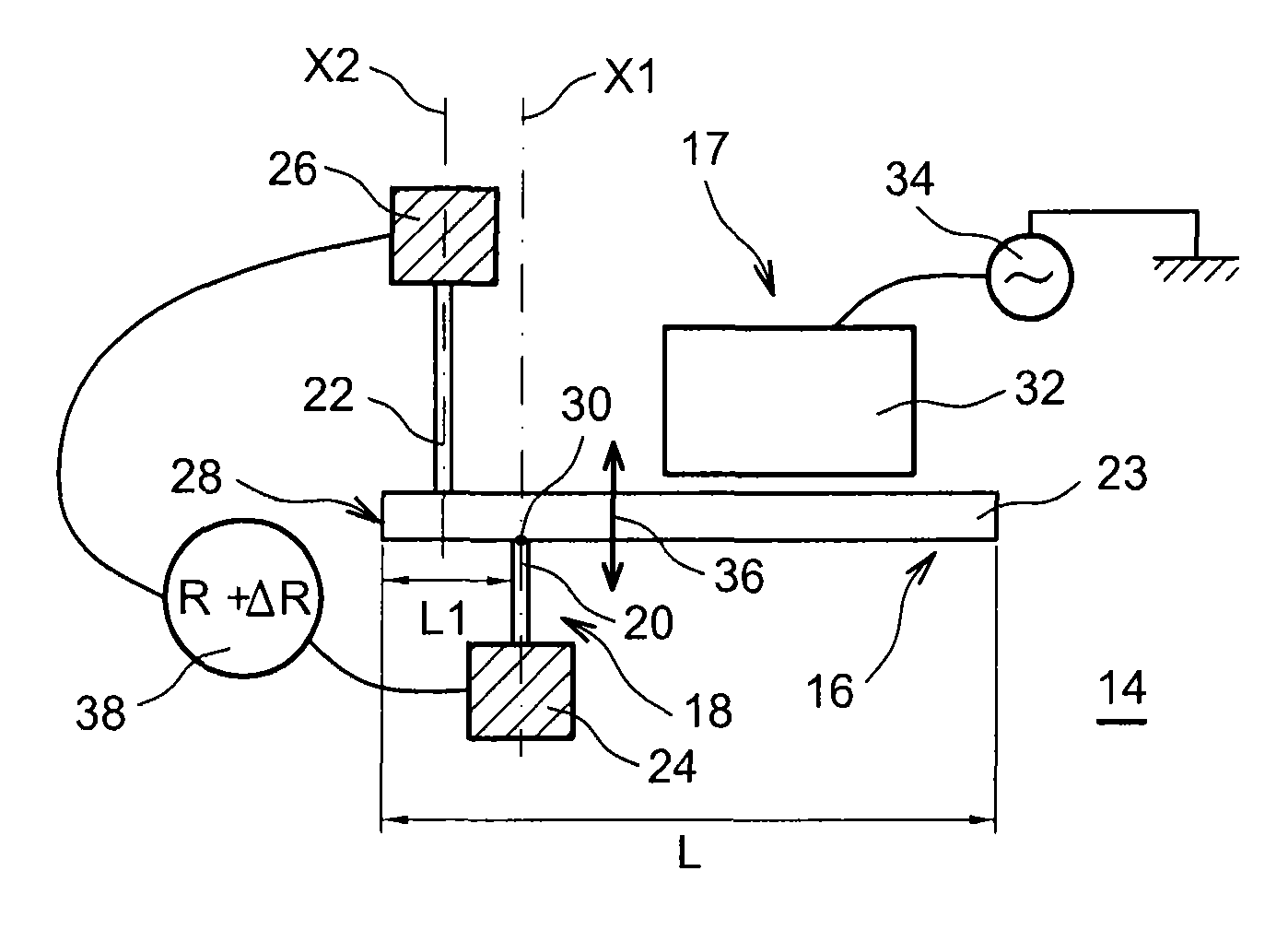
[0048]The object of the present invention is a resonant device, including a resonator and means of detection of the resonator's displacement, where these detection means include at least one piezoresistive gauge.

[0049]In this device the resonator may have a high vibration amplitude, i.e. it may have a vibration regime which remains linear across a very wide field of amplitudes, whilst permitting use of symmetrical boundary conditions, i.e. conditions which are identical at both ends of the resonator, and whilst minimising loss of strain in an anchoring.

[0050]To accomplish this the resonator is anchored to the support, from which it is suspended, through at least one element which is flexurally elastic.

[0051]In addition, in a preferred embodiment of the device, spectral noise density Sx, and therefore the output noise, are low; in other words, the device's transduction gain is high.

[0052]To obtain this result, there is a leverage to amplify the force to which the piezoresistive gauge...


PUM


Abstract

A resonant device with piezoresistive detection and with a resonator connected elastically to the support of the device, and method for manufacturing the device. The device includes: a support; a suspended resonator, which moves parallel to the plane of the support; an actuator for actuating the resonator; and a detector for detecting the movement, including at least one piezoresistive gauge. According to the invention, the resonator is anchored to the support through at least one flexurally elastic element, to enable the threshold where a non-linear displacement regime appears to be raised. The device can be manufactured by a surface technology, and applies notably to resonant mass sensors.

Description

TECHNICAL FIELD[0001]The present invention relates to a resonant device, with piezoresistive detection, together with a method for manufacturing the device.[0002]The invention finds applications notably in the field of oscillators for time bases and in the field of MEMS-type (Micro-Electro-Mechanical Systems) or NEMS-type (Nano-Electro-Mechanical Systems) sensors.[0003]It applies, for example, to resonant sensors, and in particular to mass sensors.STATE OF THE PRIOR ART[0004]For all these applications, performance (for example, mass resolution) depends on the stability of the frequency of the resonator contained in the device, and is proportional to the signal-to-noise ratio, which is noted SNR.[0005]Considering the displacement of the resonator, SNR can be expressed as the ratio P0 / Sx. In this ratio, Sx is the spectral noise density and P0 the power of the carrier wave, which is equal to half the square of the resonator's vibration amplitude A.[0006]To improve the resonator's perfo...

Claims


Application Information

Patent Timeline
Patent Type & Authority Patents(United States)
IPC IPC(8): H03H9/09H03H9/24G01H17/00H03H9/02
CPCH03H9/02259G01H17/00H03H9/2405H03H9/2447H03H2009/0244H03H2009/02496
Inventor HENTZ, SEBASTIEN
Owner COMMISSARIAT A LENERGIE ATOMIQUE ET AUX ENERGIES ALTERNATIVES
Why Eureka
Try Eureka