UVC air decontamination system

Inactive Publication Date: 2016-05-03
LICHTBLAU GEORGE J
View PDF8 Cites 6 Cited by
  • Summary
  • Abstract
  • Description
  • Claims
  • Application Information

AI Technical Summary

Problems solved by technology

UVC radiation is harmful to persons and therefore an ultraviolet radiation system such as described in the aforementioned patent are not intended to be operated with people present in the vicinity of the emitted radiation.

Method used


Image

  • UVC air decontamination system
  • UVC air decontamination system
  • UVC air decontamination system

Examples


Embodiment Construction

[0011]The content of U.S. Pat. No. 8,791,441 entitled Ultraviolet Radiation System is herein incorporated by reference in its entirety for all purposes.

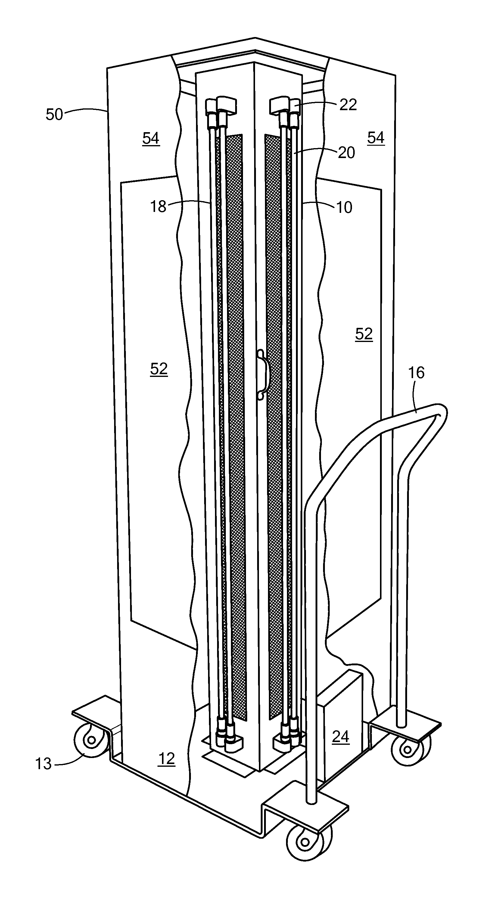
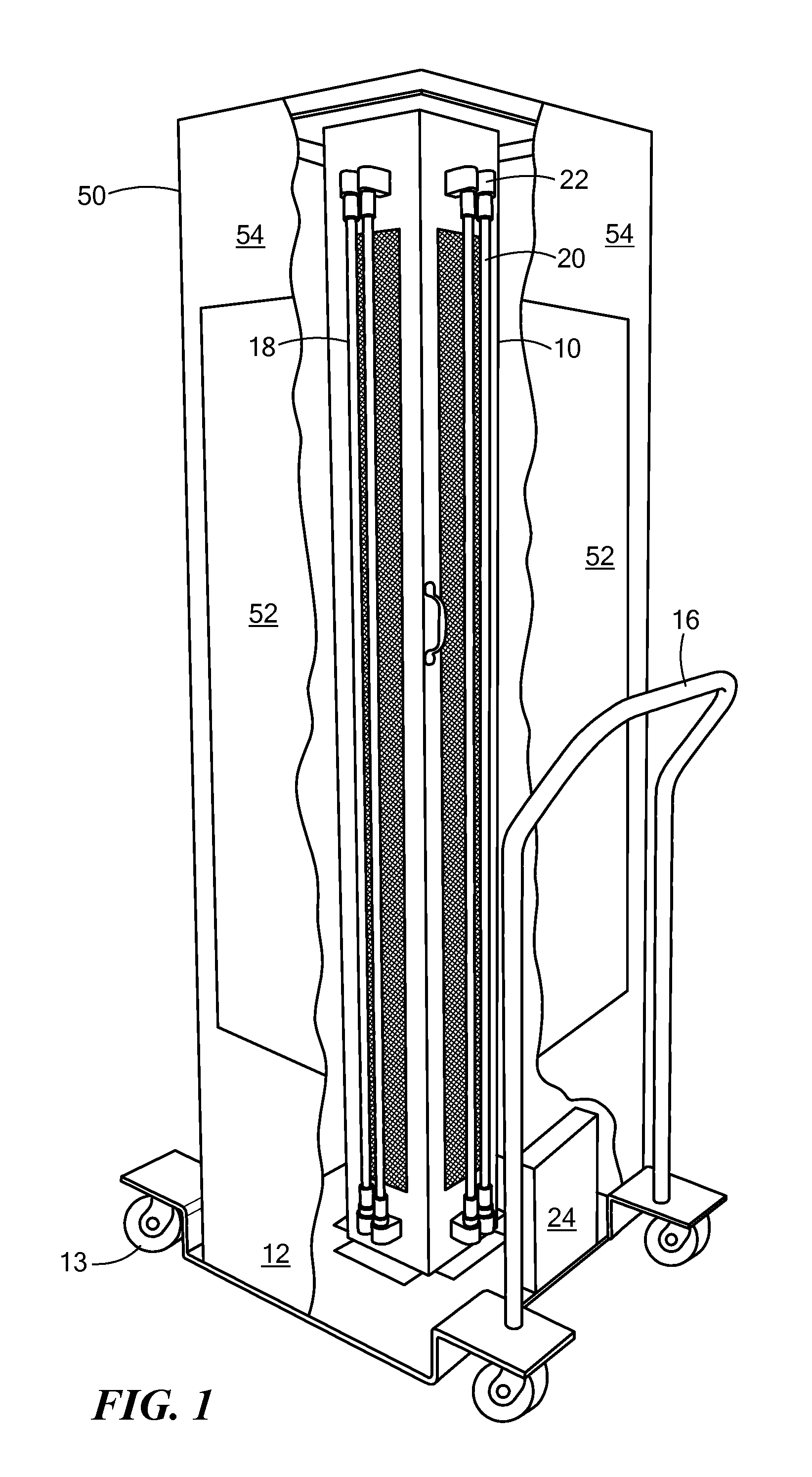
[0012]One embodiment of an ultraviolet radiation system in accordance with the invention is illustrated in FIG. 1. A square enclosure or housing 10 is supported on a wheeled base or dolly 12 having four wheels or casters 13 positioned at corners of the base as shown. A handle 16 may be positioned on a side of the base as shown for ease of movement of the system The enclosure 10 has air vent openings 18 through each side wall of the enclosure as described below. One or more UVC lamps 20 are disposed at each side wall of the enclosure 10 and are electrically and mechanically mounted to the enclosure by connectors 22. The lamps are typically low pressure, high power mercury or amalgam vapor lamps which radiate UVC radiation. The one or more lamps at each side wall of the enclosure confront the vent openings in the respective side walls ...


PUM

PropertyMeasurementUnit
wavelengthaaaaaaaaaa
heightaaaaaaaaaa
heightaaaaaaaaaa

Abstract

A UVC radiation system for producing decontaminated air which flows into the surroundings of the system while blocking UVC radiation from entering the surrounding environment. In one embodiment, the system comprises a first housing forming a first air chamber and having multiple side walls each having one or more UVC lamps adjacent thereto. Each side wall has air vent openings in a pattern which confronts substantially the entire length of the one or more adjacent lamps. A second housing surrounds the first housing and lamps and forms a second air chamber having one or more walls containing an air filter to permit air to flow through the filter into the surrounding environment and to prevent UVC radiation from entering the environment.

Description

STATEMENT REGARDING FEDERALLY SPONSORED RESEARCH OR DEVELOPMENT[0001]N / ACROSS REFERENCE TO RELATED APPLICATIONS[0002]N / ABACKGROUND OF THE INVENTION[0003]An ultraviolet radiation system is described in U.S. Pat. No. 8,791,441 by the same inventor as the present invention which provides UVC radiation at a wavelength of 253.7 nm which is effective to kill or deactivate pathogens on surfaces irradiated by the emitted UVC radiation and simultaneously effective to decontaminate air which passes uniformly over the entire length of the UVC lamps. Uniformly flowing air cools the lamps to maximize the conversion efficiency of the power input to the lamps to UVC radiation from the lamps, and at the same time decontaminates the flowing air such that air in the room is also decontaminated. UVC radiation is harmful to persons and therefore an ultraviolet radiation system such as described in the aforementioned patent are not intended to be operated with people present in the vicinity of the emitt...

Claims


Application Information

Patent Timeline
Patent Type & Authority Patents(United States)
IPC IPC(8): A61L9/20
CPCA61L9/20A61L2209/14
Inventor LICHTBLAU, GEORGE J.
Owner LICHTBLAU GEORGE J
Why Eureka
Try Eureka