
Drainage structure of corrugated fin-type heat exchanger

a heat exchanger and drain structure technology, applied in the direction of defrosting, domestic cooling apparatus, application, etc., can solve the problems of heat exchange performance drop, and achieve the effect of suppressing the adverse effect of airflow resistance, sufficient drainage, and heat exchange efficiency

Active Publication Date: 2016-05-03
SHARP KK +1
View PDF21 Cites 4 Cited by
  • Summary
  • Abstract
  • Description
  • Claims
  • Application Information

AI Technical Summary

Benefits of technology

The patent explains how to improve the efficiency of heat exchangers by preventing water from accumulating on the surface of the fins. This is important because water can cause airflow resistance and lower the heat exchange efficiency. The invention provides a solution even when the heat exchange tubes are arranged horizontally.

Problems solved by technology

As a result, there arises a problem of decrease in heat exchange performance.

Method used


Image

  • Drainage structure of corrugated fin-type heat exchanger
  • Drainage structure of corrugated fin-type heat exchanger
  • Drainage structure of corrugated fin-type heat exchanger

Examples


second embodiment

[0060]According to the drain structure of the second embodiment having the above-mentioned configuration, when the surface of the heat exchanger becomes wet, under a state in which the condensed water (dew water) in the form of water droplets, which is condensed on the surface of the corrugated fin 4, is retained between the corrugated fins 4 adjacent to the upper and lower sides of the heat exchange tube 3, the edge portions of the groove portions 11 (11A) {water flow passages 10B (11C)} are brought into contact with the retained water, and therefore serve as a water-falling origin. As a result, the water can be induced and drained to the lower corrugated fin 4. Subsequently, in the same manner, the condensed water (dew water) in the form of water droplets, which is condensed on the surface of the corrugated fin 4, is sequentially drained to the lower corrugated fin 4.

[0061]According to the drain structures of the first and second embodiments having the above-mentioned configuratio...

third embodiment

[0068]The above-mentioned third embodiment has described the case where the drain assisting member 100 is formed of a single wire, but a drain assisting member having a different shape may be used.

fourth embodiment

[0069]For example, in a fourth embodiment illustrated in FIG. 11, a drain assisting member 20 has a shape in which a plurality of linear materials 21 made of aluminum, for example, two or three linear materials 21 (FIG. 11 illustrate a case of three linear materials 21), are twisted together, and the water passage is formed in a clearance 22 defined among the respective linear materials 21. In this case, the clearance 22 is positioned on the inner side of the side end of the corrugated fin 4.

[0070]According to the structure of the fourth embodiment having the above-mentioned configuration, as illustrated in FIG. 11(b), by the capillary phenomenon, the water droplets adhering to the corrugated fin 4 run into the drain assisting member 20 arranged in the vicinity thereof from an open peak portion 4a of a corrugated shape, that is, a peak-4a-to-valley-4b shape, and are drained to the lower corrugated fin 4 with the gap of the drain assisting member 20 itself, that is, the clearance 22 ...


PUM


Abstract

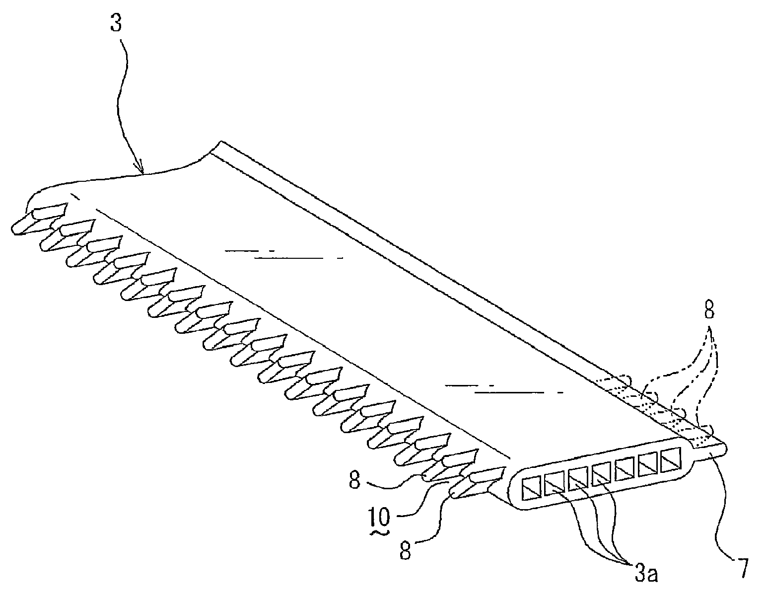
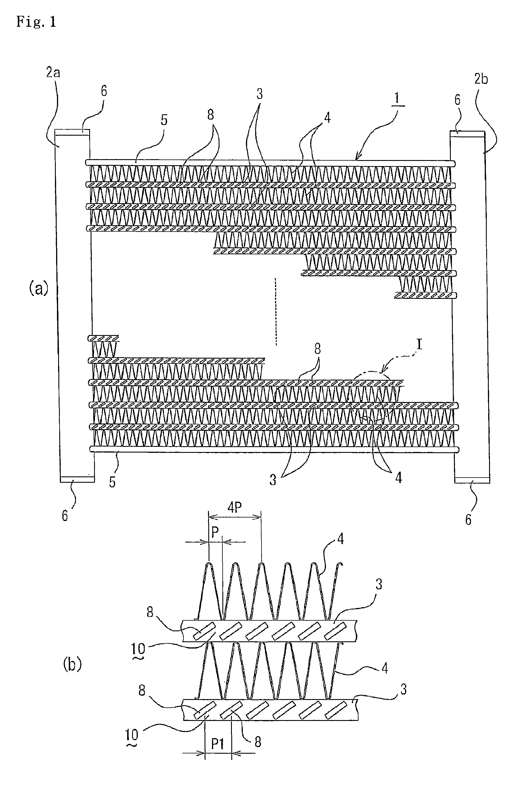
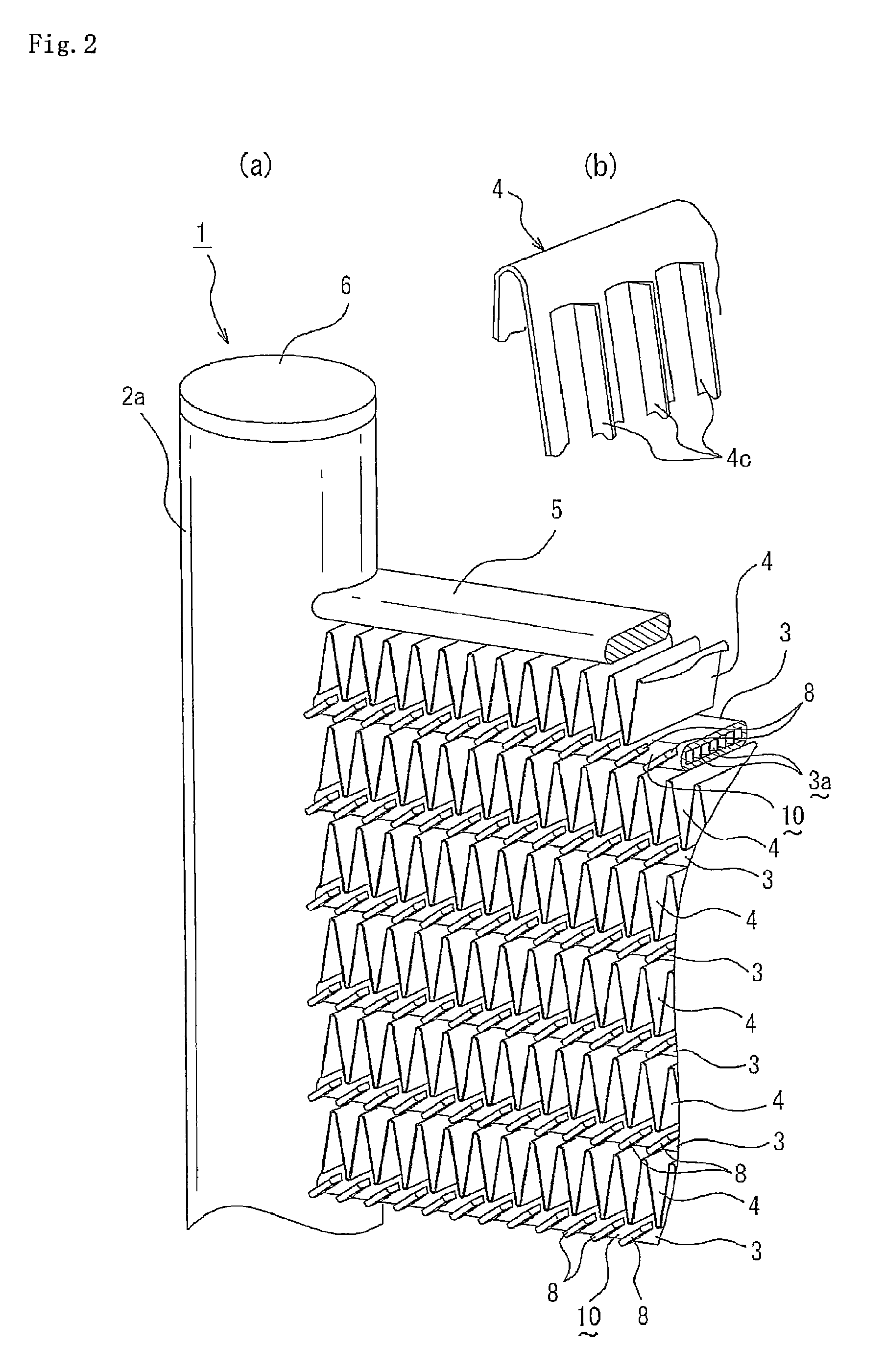
A drain structure for a corrugated fin-type heat exchanger, the corrugated fin-type heat exchanger being constituted by arranging a plurality of flat heat exchange tubes parallel to one another in a horizontal direction between a pair of opposing header pipes, and joining corrugated fins between the plurality of flat heat exchange tubes, the drain structure including a plurality of water flow passages for inducing water retained between the corrugated fins adjacent to an upper side and a lower side of each of the plurality of flat heat exchange tubes, the plurality of water flow passages being formed on an outer end surface of the each of the plurality of flat heat exchange tubes in a width direction thereof at a pitch along a longitudinal direction of the each of the plurality of flat heat exchange tubes.

Description

TECHNICAL FIELD[0001]The present invention relates to a drain structure for a corrugated fin-type heat exchanger, and more specifically, to a drain structure which achieves improvement in drainage of a parallel flow heat exchanger having corrugated fins and flat heat exchange tubes alternately arranged therein.BACKGROUND ART[0002]In general, a corrugated fin-type heat exchanger is widely used, which is constituted by arranging a plurality of flat heat exchange tubes parallel to one another in a horizontal direction between a pair of opposing header pipes, and joining corrugated fins between the heat exchange tubes. In a case where the corrugated fin-type heat exchanger of this kind is used as an evaporator, for example, condensed water (dew water) adheres to the surface thereof, which increases an airflow resistance, and further, inhibits heat transfer due to a resistance of a water film adhering to the surfaces of the corrugated fins. As a result, there arises a problem of decrease...

Claims


Application Information

Patent Timeline
Patent Type & Authority Patents(United States)
IPC IPC(8): F25D21/14F28D1/053F28F1/12F28F1/34F28F17/00
CPCF28F17/005F28D1/05383F28F1/128F28F1/022F25B39/02F28F1/26F28F1/30F28F17/00
Inventor FURUMAKI, MASAYUKIYOSHIDA, TAKESHIYAMAZAKI, KAZUHIKO
Owner SHARP KK
Learn More