
Method and apparatus for efficient and transparent network management and application coordination for software defined optical switched data center networks

a data center network and software-defined technology, applied in data switching networks, wavelength-division multiplex systems, multiplex communication, etc., can solve the problems of high redundancy of switches and cables, inability to meet the characteristics of today's global data center network traffic, and limited bandwidth to the remote areas

Inactive Publication Date: 2016-05-03
LIU GUOHUA
View PDF18 Cites 8 Cited by
  • Summary
  • Abstract
  • Description
  • Claims
  • Application Information

AI Technical Summary

Benefits of technology

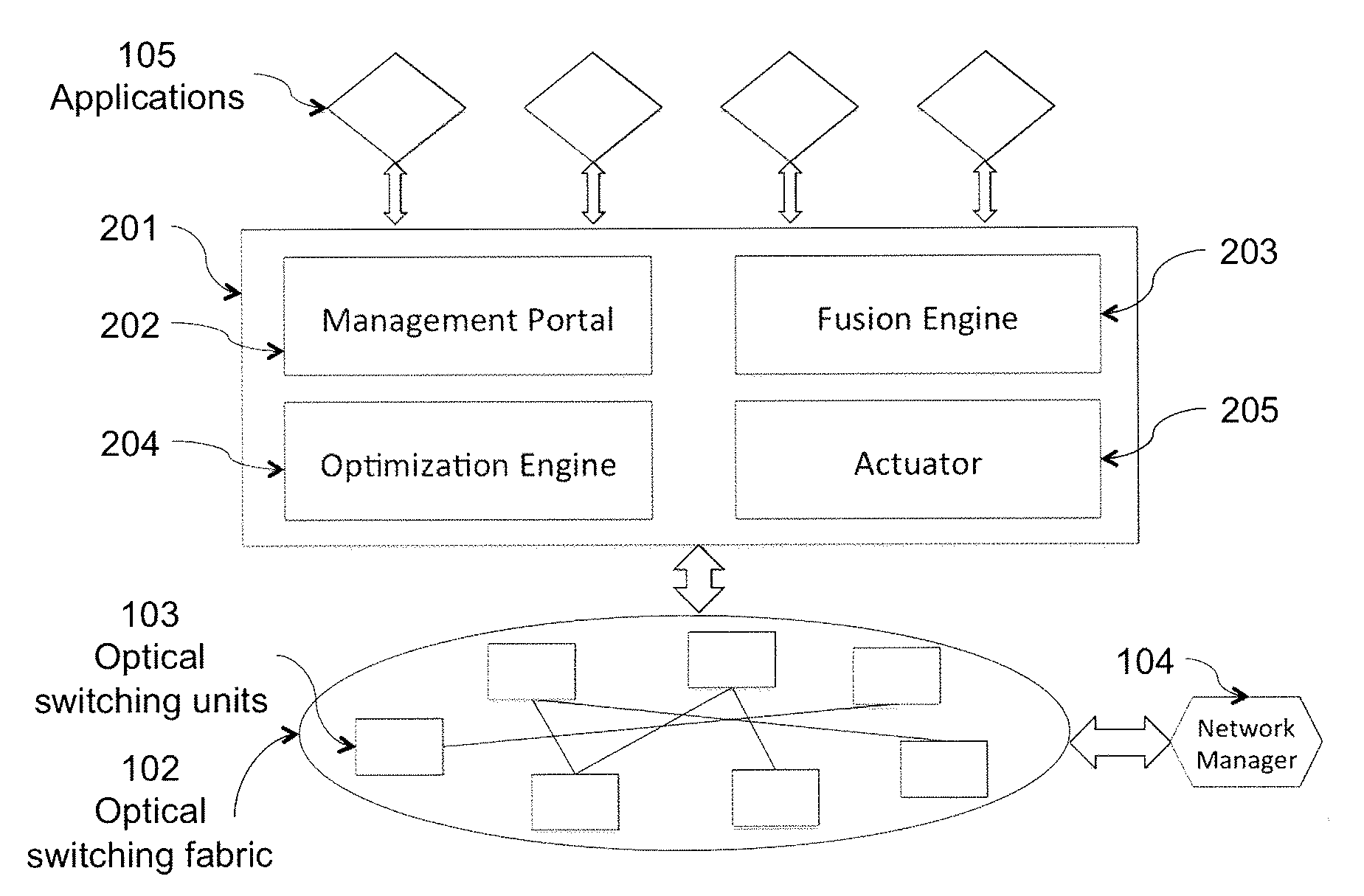
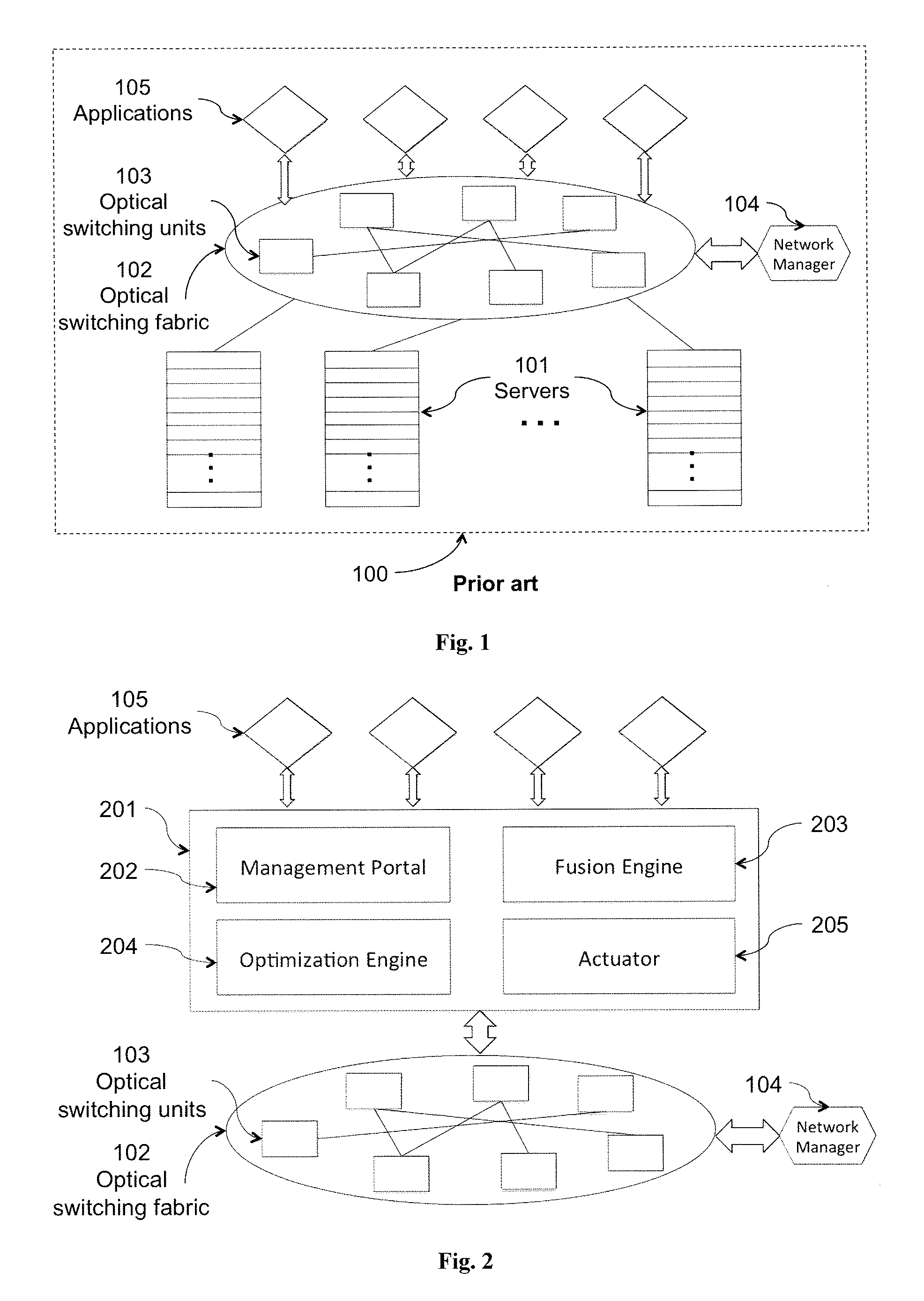
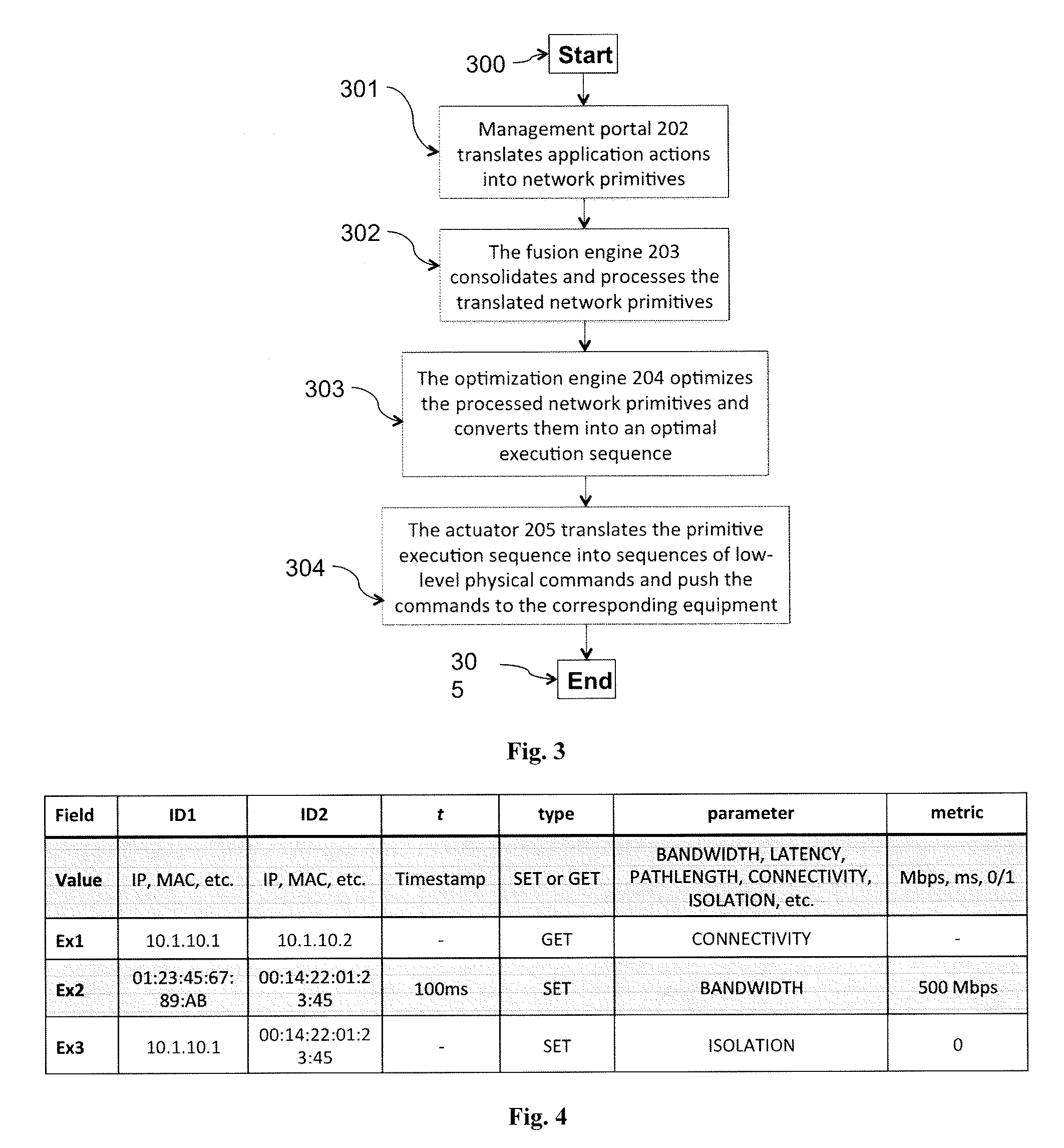
The patent describes a method and system for optimizing application actions in an optical switching fabric. The system receives actions from distributed applications and translates them into network operation primitives, which are then processed to determine an optimized set of network operation primitives. The optimal execution sequence is determined and the optimized set of network operation primitives is executed on the optical switching fabric. The technical effect is to improve the performance and efficiency of the optical switching fabric by optimizing the execution of application actions.

Problems solved by technology

The conventional over-subscribed tree-like architectures of data center networks provide abundant network bandwidth to the local areas of the hierarchical tree, but provide scarce bandwidth to the remote areas.
For this reason, such conventional architectures are unsuitable for the characteristics of today's global data center network traffic.
These systems use highly redundant switches and cables to achieve high network throughput.
However, these designs have several key limitations.
First, the redundant switches and cables significantly increase the cost for building the network architecture.
Second, the complicated interconnections lead to high cabling complexity, making such designs infeasible in practice.
These proposals suffer from similar drawbacks.
However, the optical switching matrix or Microelectromechanical systems (MEMS) component in OSA significantly increases the cost of the proposed architecture and more importantly limits the applicability of OSA to only small or medium sized data centers.

Method used


Image

  • Method and apparatus for efficient and transparent network management and application coordination for software defined optical switched data center networks
  • Method and apparatus for efficient and transparent network management and application coordination for software defined optical switched data center networks
  • Method and apparatus for efficient and transparent network management and application coordination for software defined optical switched data center networks

Examples


Embodiment Construction

[0030]The present invention will now be described in detail with reference to the drawings, which are provided as illustrative examples of the invention as to enable those skilled in the art to practice the invention. The figures and examples below are not meant to limit the scope of the present invention to a single embodiment, but other embodiments are possible by way of interchange of some or all of the described or illustrated elements. Moreover, where some of the elements of the present invention can be partially or fully implemented using known components, only portions of such known components that are necessary for an understanding of the present invention will be described, and a detailed description of other portions of such known components will be omitted so as not to obscure the invention. Embodiments described as being implemented in software should not be limited thereto, but can include embodiments implemented in hardware, or a combination of hardware and software, a...


PUM


Abstract

Application actions are optimized by receiving actions from one or more distributed applications, translating the received actions into one or more network operation primitives, processing the network operation primitives to determine an optimized set of network operation primitives, determining an optimal execution sequence for the optimized set of network operation primitives, and executing the optimized set of network operation primitives based on the optimal execution sequence.

Description

CROSS-REFERENCE TO RELATED APPLICATIONS[0001]This application claims priority to U.S. Provisional Patent Application No. 61 / 777,675 filed Mar. 12, 2013, which is incorporated herein by reference.[0002]This patent application is related to U.S. Provisional Patent Application No. 61 / 719,026 filed Oct. 26, 2012, now U.S. application Ser. No. 14 / 057,133 filed Oct. 18, 2013, published as U.S. Patent Application Publication No. 2014 / 0119728. Substantive portions of U.S. Provisional Patent Application No. 61 / 719,026 are attached hereto in an Appendix to the present application. U.S. Provisional Patent Application No. 61 / 719,026 is incorporated herein by reference.BACKGROUND OF THE INVENTION[0003]The present invention relates generally to network management systems, and, more particularly, to self-optimizing systems and methods for managing and coordinating a plurality of applications deployed on an optical-switched data center network.[0004]In the past several years, designing the next-gen...

Claims


Application Information

Patent Timeline
Patent Type & Authority Patents(United States)
IPC IPC(8): H04Q11/00H04L12/721H04J14/02H04J14/00H04L12/24H04L12/729H04L12/931H04L45/125
CPCH04Q11/0005H04J14/0204H04J14/0257H04J14/0267H04L41/0823H04L45/125H04L45/62H04L49/356H04L41/40
Inventor XU, LEIZHANG, YUEPING
Owner LIU GUOHUA
Learn More