Check patentability & draft patents in minutes with Patsnap Eureka AI!

Low suction pressure protection for refrigerant vapor compression system

a technology of refrigerant vapor compression and low suction pressure protection, which is applied in the field of refrigeration systems, can solve the problems of transport refrigerant vapor compression systems that are subject to cycling between operating mode and standstill mode, and achieve the effect of increasing the superheat valu

Active Publication Date: 2016-05-10
CARRIER CORP
View PDF31 Cites 7 Cited by
  • Summary
  • Abstract
  • Description
  • Claims
  • Application Information

AI Technical Summary

Benefits of technology

The system effectively prevents solid-phase refrigerant formation, allowing continuous operation below the triple point pressure, enhancing system efficiency and preventing damage to components, thereby expanding the operational range of the refrigerant vapor compression system.

Problems solved by technology

Additionally, transport refrigerant vapor compression systems are subject to cycling between an operating mode and standstill mode, i.e. an idle state.
The solid phase refrigerant may damage components or cause inefficiencies, which is undesirable.

Method used


Image

  • Low suction pressure protection for refrigerant vapor compression system
  • Low suction pressure protection for refrigerant vapor compression system
  • Low suction pressure protection for refrigerant vapor compression system

Examples


Embodiment Construction

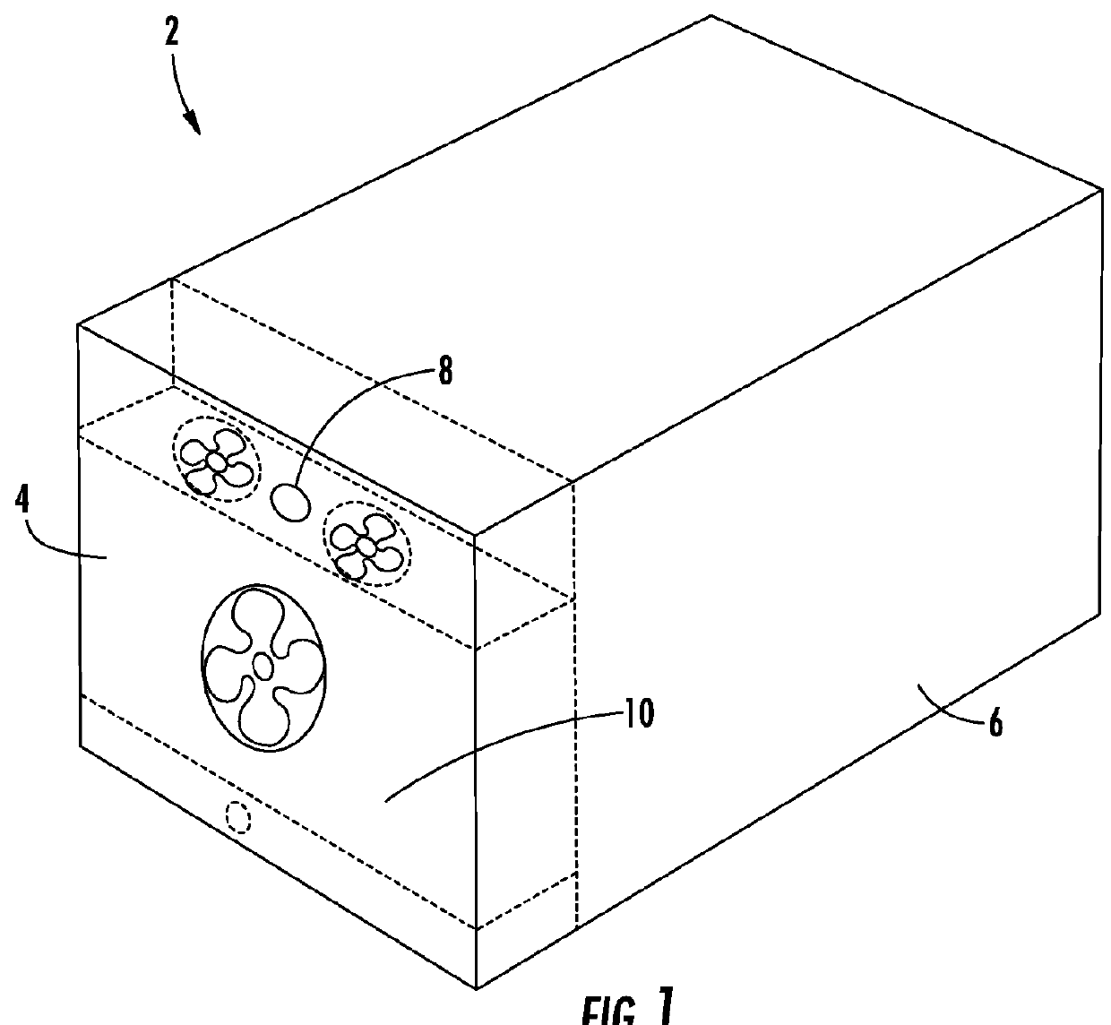
[0022]Referring to FIG. 1, a refrigerant vapor compression system 2 may include a transport refrigeration unit 4 coupled to an enclosed space within a container 6. The container 6 may be a temperature controlled environment, such as a cargo box of a refrigerated transport truck, trailer or container, or a display case, merchandiser, freezer cabinet, cold room or other perishable / frozen product storage area in a commercial establishment, or a climate controlled comfort zone within a residence, office building, hospital, school, restaurant or other facility. In the disclosed example, the refrigerant vapor compression system 2 is of the type utilized on refrigerated transport truck. As shown in FIG. 1, the transport refrigeration unit 4 is configured to maintain a programmed thermal environment within the container 6.

[0023]In FIG. 1, the transport refrigeration unit 4 is mounted at one end of the container 6. However, the transport refrigeration unit 4 may also be mounted to one or mor...


PUM


Abstract

The present disclosure provides a refrigerant vapor compression system includes a compressor (12) having a suction port and a discharge port, a refrigerant heat rejection heat exchanger (24) operatively coupled downstream to the discharge port of the compressor, a refrigerant heat absorption heat exchanger (42) operatively coupled downstream to the refrigerant heat rejection heat exchanger, a compressor suction inlet line connecting the refrigerant heat absorption heat exchanger to the suction port of the compressor, and an adiabatic expansion device (54) operatively coupled to the suction inlet line. A sensor operatively coupled to the suction inlet line measures a superheat value of the refrigerant. The refrigerant vapor compression system further includes a controller (60) in communication with the sensor. The controller is configured to operate the refrigerant vapor compression system in a first mode when a pressure of the refrigerant downstream of the adiabatic expansion device is greater than a threshold value, and operate the refrigerant vapor compression system in a second mode when the pressure of the refrigerant downstream of the adiabatic expansion device is less than the threshold value. The compressor continues to operate in both the first mode and the second mode.

Description

CROSS-REFERENCE TO RELATED APPLICATION[0001]Reference is made to and this application claims priority from and the benefit of U.S. Provisional Application Ser. No. 61 / 264,306, filed Nov. 25, 2009, and entitled LOW SUCTION PRESSURE PROTECTION FOR REFRIGERANT VAPOR COMPRESSION SYSTEM, which application is incorporated herein in its entirety by reference.FIELD OF THE INVENTION[0002]This disclosure relates generally to refrigeration systems and, more specifically, to a method and apparatus for controlling a refrigerant vapor compression system.BACKGROUND OF THE INVENTION[0003]Conventional vapor compression systems typically include a compressor, a heat rejection heat exchanger, a heat absorption heat exchanger, and an expansion device disposed upstream of the heat absorption heat exchanger. Some systems further include a second expansion device downstream of the heat rejection heat exchanger, such as a suction modulation valve. These basic system components are interconnected by working...

Claims


Application Information

Patent Timeline
Patent Type & Authority Patents(United States)
IPC IPC(8): F25B49/02F25B1/00F25B9/00F25B41/04F25B1/10
CPCF25B41/043F25B9/008F25B49/02F25B2700/1931F25B2700/1933F25B2700/2106F25B2700/21151F25B2700/21152F25B1/10F25B2309/06F25B2341/065F25B2341/0662F25B2400/01F25B2400/13F25B2700/21172F25B2700/21175Y02B30/72F25B2400/23F25B2600/0261F25B2600/0272F25B2600/2509F25B2600/2513F25B2700/151F25B2700/197Y02B30/70F25B41/34F25B41/22F25B41/39
Inventor HUFF, HANS-JOACHIMDURAISAMY, SURESH
Owner CARRIER CORP
Features
  • R&D
  • Intellectual Property
  • Life Sciences
  • Materials
  • Tech Scout
  • Unparalleled Data Quality
  • Higher Quality Content
  • 60% Fewer Hallucinations
Learn More