Low heat rejection high efficiency internal combustion engine

a high-efficiency, internal combustion engine technology, applied in the direction of machines/engines, mechanical equipment, coatings, etc., can solve the problems of unsuitability, unsuitability, and low amount of energy stored in the insulation material, and achieve the effect of low heat rejection rate, less heat loss, and high efficiency

Inactive Publication Date: 2009-03-19
DWIGHT ENGINE TECHNOLGIES
View PDF42 Cites 34 Cited by
  • Summary
  • Abstract
  • Description
  • Claims
  • Application Information

AI Technical Summary

Benefits of technology

[0005]In view of the foregoing, an object of the present invention is to provide a high efficiency ICE that is operable to run with relatively low heat rejection rates. In embodiments of ICEs described herein, an insulating liner is provided to limit the heat flow from the combustion gases to the surrounding engine components. The insulating liner may include portions lining the top of a piston and the combustion chamber. The insulating liner may also include portions along a region of the cylinder wall and may be configured to balance insulation performance with mechanical performance. In this regard, the insulating liner on the cylinder wall may be placed in a region close to the combustion chamber where the maximum heat flow through the cylinder wall typically occurs. Regions of the cylinder wall more distal to the combustion chamber, where typically less heat loss occurs, may be constructed using standard cylinder wall materials (e.g., cast iron). Piston rings disposed on a piston may be positioned so that they do not come into contact with the insulating cylinder wall liner. In this regard, the size of the cylinder wall liner and position of the piston rings may be selected to balance insulation performance with mechanical performance and simplicity.

Problems solved by technology

In embodiments of ICEs described herein, the lower temperature exhaust gases and corresponding reduced energy loss may render turbocharging unnecessary and / or unsuitable.
The low heat capacity results in a relatively low amount of energy being stored in the insulation material during any particular engine cycle.
This is in part due to the relatively low amount of energy stored in the insulation that is available for transfer to the incoming gases.

Method used


Image

  • Low heat rejection high efficiency internal combustion engine
  • Low heat rejection high efficiency internal combustion engine
  • Low heat rejection high efficiency internal combustion engine

Examples


Embodiment Construction

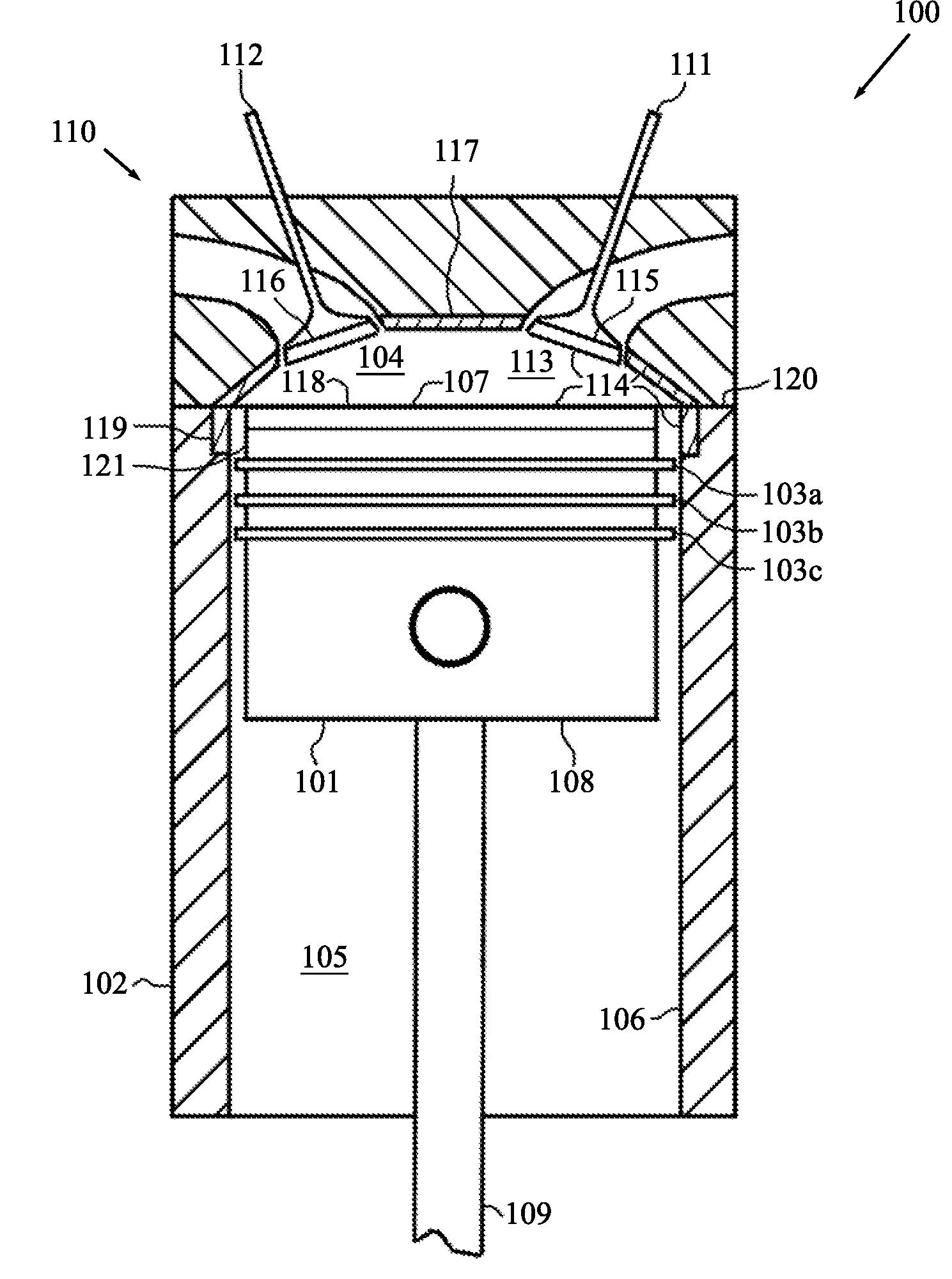
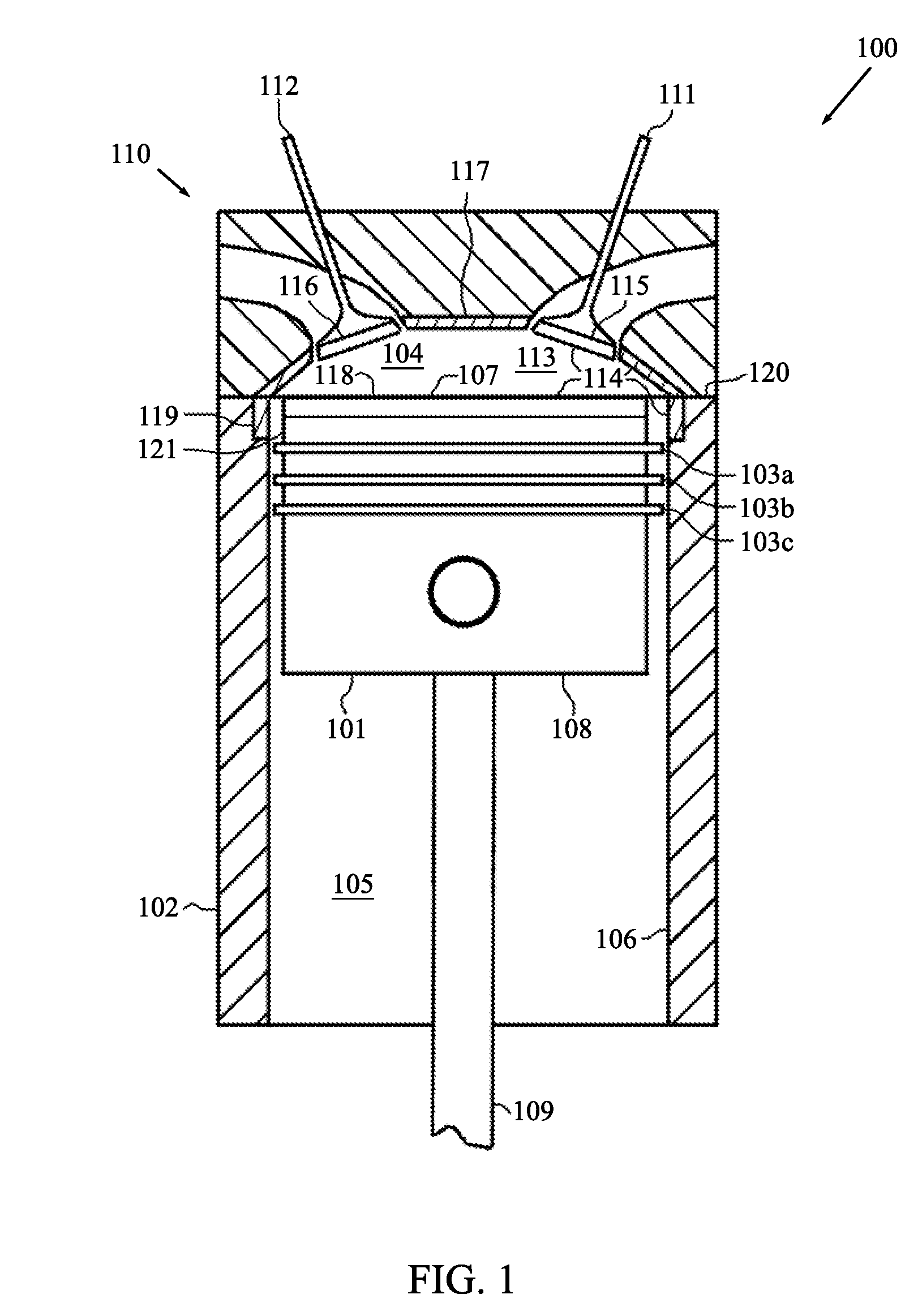
[0028]FIG. 1 is a cross-sectional schematic diagram of a portion of an ICE 100. The portion 100 includes a piston 101 disposed in a cylinder 102. The ICE 100 may contain additional similarly configured pistons and cylinders. A set of piston rings 103a, 103b, and 103c is interconnected to the piston 101. The set of piston rings 103a, 103b, and 103c restricts the flow of material (e.g., combustion gases) between a volume 104 above the piston rings 103a, 103b, and 103c and a volume 105 below the piston rings 103a, 103b, and 103c. The piston rings 103a, 103b, and 103c also remain in contact with the cylinder wall 106 and help to minimize contact between the piston 101 and the cylinder wall 106. In this regard, it is beneficial to situate the uppermost piston ring 103a closer to the top 107 of the piston 101 then to the bottom 108 of the piston 101. In this manner, the piston rings 103a, 103b, and 103c assist in keeping the piston 101 aligned with in the cylinder 102 and prevent the top ...


PUM

PropertyMeasurementUnit
thicknessaaaaaaaaaa
thermal conductivityaaaaaaaaaa
operating temperatureaaaaaaaaaa

Abstract

An internal combustion engine including a low thermal capacity, low thermal conductivity insulating liner is provided. The insulating liner may be positioned to line the combustion chamber and a portion of the cylinder wall. The insulating liner may comprise a high aspect morphology sintered ceramic material and may further include a surface coating. The internal combustion engine may be a four-stroke diesel engine with variable valve timing operating using an asymmetric cycle. Through the asymmetric cycle and insulative properties of the insulating liner, the heat loss of the disclosed internal combustion engine is significantly less than that of a similar conventional internal combustion engine, resulting in significant efficiency improvements.

Description

RELATED APPLICATIONS[0001]This application claims priority from U.S. Provisional Patent Application Ser. No. 60 / 973,672, filed Sep. 19, 2007, entitled “Low Heat Rejection High Efficiency Internal Combustion Engine,” the entire disclosure of which is incorporated by reference in its entirety herein.FIELD OF THE INVENTION[0002]The present invention relates to internal combustion engines (“ICEs”), and more particularly to high efficiency ICEs capable of running at relatively low heat rejection rates and related methods.BACKGROUND OF THE INVENTION[0003]A typical ICE will have cooling losses in the order of 30 to 40 percent of the total losses of the engine. In an attempt to minimize these losses, combustion chamber insulation has been proposed. The insulation typically has the effect of raising the temperature within the combustion chamber since less of the heat energy of combustion is able to escape the chamber through the chamber walls and be transferred to a cooling system. The highe...

Claims


Application Information

Patent Timeline
Patent Type & Authority Applications(United States)
IPC IPC(8): F02F3/16
CPCF02B77/02F02B77/11Y02T10/142F05C2203/08F05C2253/12F02F7/0087Y02T10/12
Inventor MACMILLAN, SHAUN T.DWIGHT, BARTON R.
Owner DWIGHT ENGINE TECHNOLGIES
Why Eureka
Try Eureka