Refrigerant vapor compression system with intercooler

a technology of refrigerant vapor compression and intercooler, which is applied in the direction of refrigeration components, indirect heat exchangers, lighting and heating apparatus, etc., can solve the problems of complicating the incorporation of an intercooler into the refrigerant circuit, and may not be practical in some situations, so as to improve the energy efficiency and cooling capacity of the refrigerant vapor compression system

Active Publication Date: 2013-02-07
CARRIER CORP
View PDF18 Cites 38 Cited by
  • Summary
  • Abstract
  • Description
  • Claims
  • Application Information

AI Technical Summary

Benefits of technology

[0009]An intercooler is incorporated into a refrigeration vapor compression system having at least a two stage compression device in such a manner as to improve energy efficienc

Problems solved by technology

However, incorporating an intercooler into a refrigerant vapor compression system in accord with previous practice may not be practical in some situations, for example due to physical space, weight and equipment cost considerations.
The higher refr

Method used


Image

  • Refrigerant vapor compression system with intercooler
  • Refrigerant vapor compression system with intercooler
  • Refrigerant vapor compression system with intercooler

Examples


Embodiment Construction

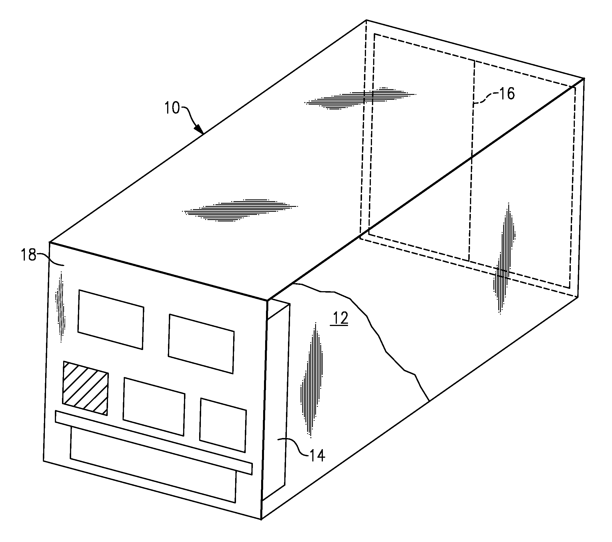
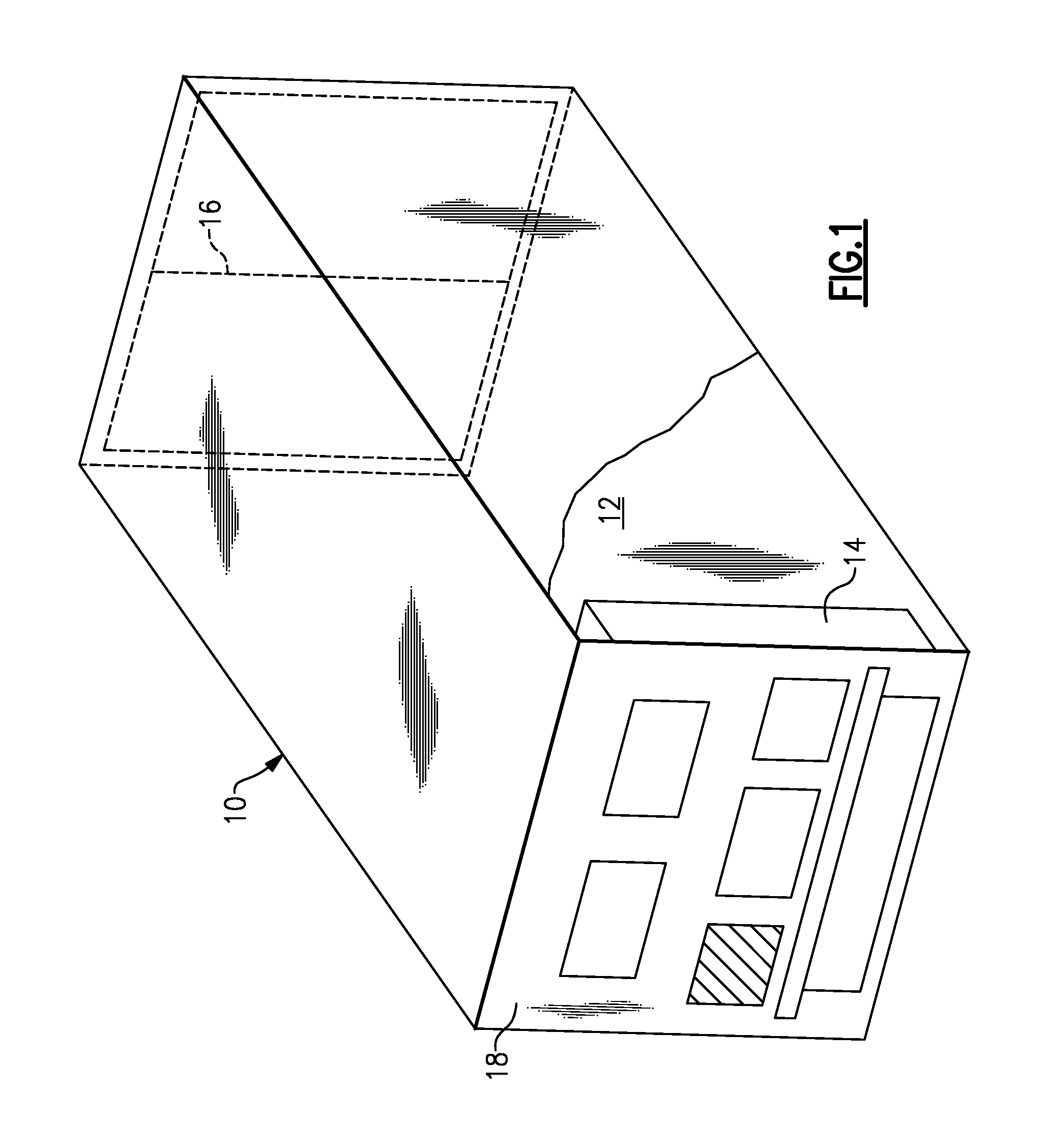
[0024]There is depicted in FIG. 1 an exemplary embodiment of a refrigerated container 10 having a temperature controlled cargo space 12 the atmosphere of which is refrigerated by operation of a refrigeration unit 14 associated with the cargo space 12. In the depicted embodiment of the refrigerated container 10, the refrigeration unit 14 is mounted in a wall of the refrigerated container 10, typically in the front wall 18 in conventional practice. However, the refrigeration unit 14 may be mounted in the roof, floor or other walls of the refrigerated container 10. Additionally, the refrigerated container 10 has at least one access door 16 through which perishable goods, such as, for example, fresh or frozen food products, may be loaded into and removed from the cargo space 12 of the refrigerated container 10.

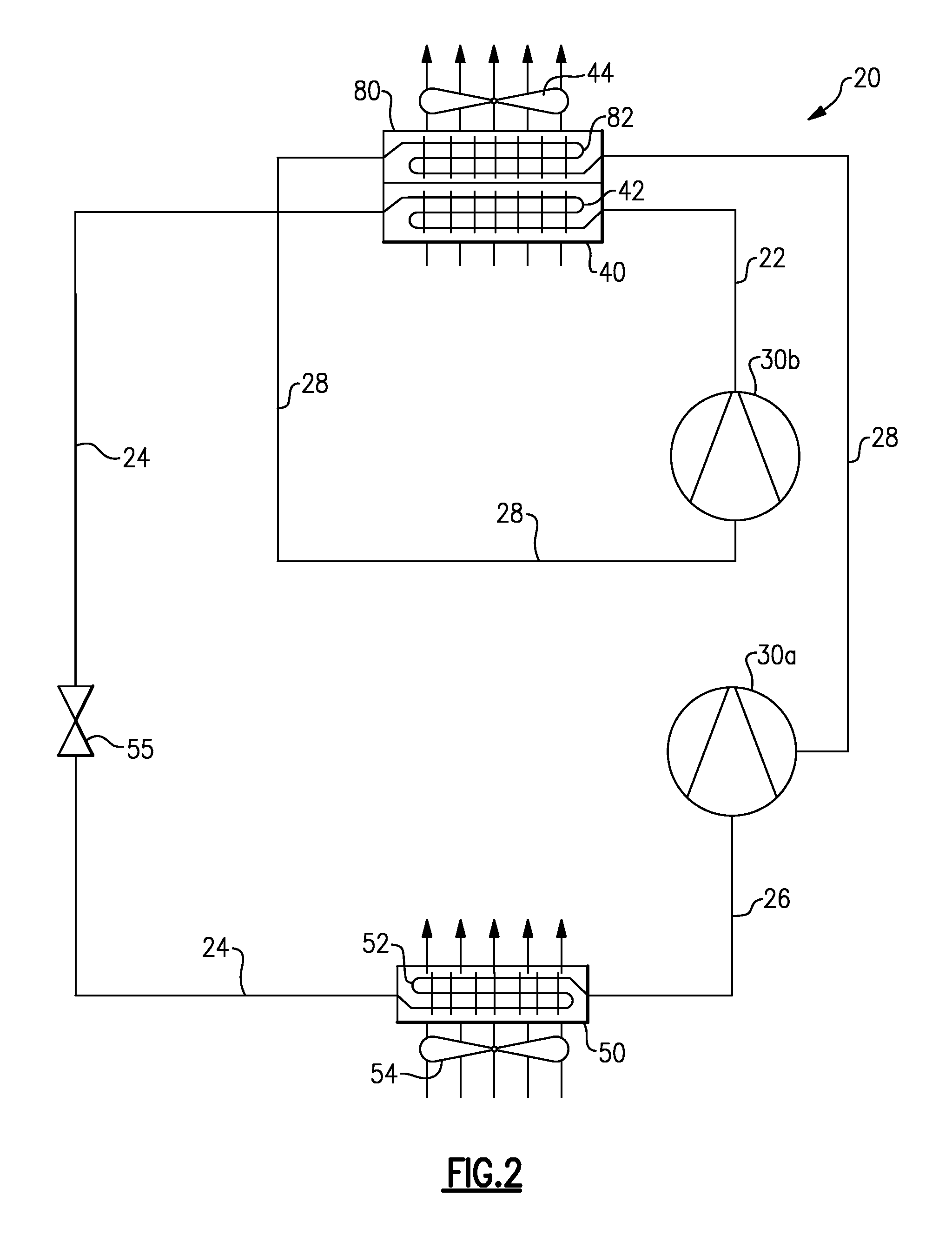
[0025]Referring now to FIGS. 2-7, there are depicted schematically various exemplary embodiments of a refrigerant vapor compression system 20 suitable for use in the refrigeration...


PUM


Abstract

A refrigerant vapor compression system includes a compression device having at least a first compression stage and a second compression stage, a refrigerant heat rejection heat exchanger disposed downstream with respect to refrigerant flow of the second compression stage, and a refrigerant intercooler disposed intermediate the first compression stage and the second compression stage. The refrigerant intercooler is disposed downstream of the refrigerant heat rejection heat exchanger with respect to the flow of a secondary fluid. A second refrigerant heat rejection heat exchanger may be disposed downstream with respect to refrigerant flow of the aforesaid refrigerant heat rejection heat exchanger, and a second refrigerant intercooler may be disposed intermediate the first compression stage and the second compression stage and downstream with respect to refrigerant flow of the aforesaid refrigerant intercooler.

Description

CROSS-REFERENCE TO RELATED APPLICATION[0001]This application claims priority to U.S. Provisional Patent Application Ser. No. 61 / 329,332 entitled “Refrigerant Vapor Compression System with Intercooler” filed on Apr. 29, 2010, the content of which is incorporated herein by reference in its entirety.FIELD OF THE INVENTION[0002]This invention relates generally to refrigerant vapor compression systems and, more particularly, to improving the energy efficiency and / or cooling capacity of a refrigerant vapor compression system incorporating a multi-stage compression device, for example a two-stage compressor, and more particularly to a refrigerant vapor compression system incorporating a two-stage compressor and an intercooler for cooling refrigerant passing between the compression stages.BACKGROUND OF THE INVENTION[0003]Refrigerant vapor compression systems are well known in the art and commonly used for conditioning air to be supplied to a climate controlled comfort zone within a residenc...

Claims


Application Information

Patent Timeline
IPC IPC(8): F25B1/10
CPCF25B1/10F25B2309/061F28D7/10F25B2400/072F25B2400/13F25B2400/04
Inventor HUFF, HANS-JOACHIMLEE, KEONWOOLIU, LUCY YIDURAISAMY, SURESHASPROVSKI, ZVONKOLAMENDOLA, KURSTENLIFSON, ALEXANDER
Owner CARRIER CORP
Why Eureka
Try Eureka